
Ray Optics and Optical Instruments | ISC Class 12 Physics Notes
On this page
This note covers reflection by spherical mirrors, refraction at plane and spherical surfaces, total internal reflection, optical fibres, lenses, lens and mirror combinations, prisms, dispersion, rainbows, microscopes and astronomical telescopes.
How do rays, images and sign conventions describe light?
Ray optics represents light by straight paths called rays. A beam is a bundle of rays. This approximation is useful when the wavelength, the distance between successive wave crests, is very small compared with the objects involved.
Reflection sends light back into its original medium. Refraction changes the direction of obliquely incident light as it crosses between transparent media. The normal is the perpendicular to the surface at the point where the ray strikes.
A real image forms where rays actually meet; a virtual image forms where their backward extensions meet. A screen receives a real image but does not create it.
How are distances and heights signed?
For a spherical mirror, the pole is its geometrical centre; the centre of curvature is the centre of the sphere of which it forms a part. The principal axis joins these points. A thin lens has an optical centre through which a ray passes without deviation.
- Measure mirror distances from the pole and thin-lens distances from the optical centre.
- Distances along the incident-light direction are positive; distances against it are negative.
- Heights above the principal axis are positive; heights below it are negative.
Use u for signed object distance, v for signed image distance, f for signed focal length, and R for signed radius of curvature. Focal length measures the distance to the principal focus, where parallel axial rays meet or appear to originate.
The SI unit of object distance is metre (m). The SI unit of image distance is metre. The SI unit of focal length is metre. The SI unit of radius of curvature is metre. Consistent centimetres (cm) also work in image-distance equations.
How do spherical mirrors form images?
A concave mirror reflects from its inward-curved surface; a convex mirror reflects from its outward-curved surface. Normals pass through their centres of curvature. Incidence and reflection angles, measured from the normal, are equal. Incident ray, normal and reflected ray lie in one plane.
Paraxial rays pass close to the principal axis and make small angles with it. For these rays, a concave mirror brings an axial parallel beam to a real focus; a convex mirror gives a virtual focus. Their focal lengths are respectively negative and positive.
Why is the focal length half the radius?
Let y be a ray's height above the axis and θ the small angle between the radius to its point of incidence and the axis. Reflection makes the returning ray incline by 2θ. Using positive lengths, y ≈ |R|θ and y ≈ 2|f|θ.
Cancelling y and θ gives |R| ≈ 2|f|. Vertical bars mean magnitude. The signed paraxial result is R = 2f. It assumes paraxial rays.
Derivation: the mirror formula
Consider a real inverted image from a concave mirror. Let U, V and Fₘ be the positive magnitudes of object distance, image distance and focal length. Let h be object height and H the positive image-height magnitude.
- Similar triangles formed by a ray reflected at the pole give H/h = V/U.
- A ray initially parallel to the axis returns through the focus. Its similar triangles give H/h = (V − Fₘ)/Fₘ.
- Equating the ratios gives V/U = V/Fₘ − 1, hence 1/U + 1/V = 1/Fₘ. Substituting U = −u, V = −v and Fₘ = −f gives the signed equation.
1/v + 1/u = 1/f. Linear magnification, m, is signed image height h′ divided by object height h: m = h′/h = −v/u. Negative values mean inversion; positive values mean an erect image. Magnification has no unit.
What the figure shows
Concave-mirror image formation
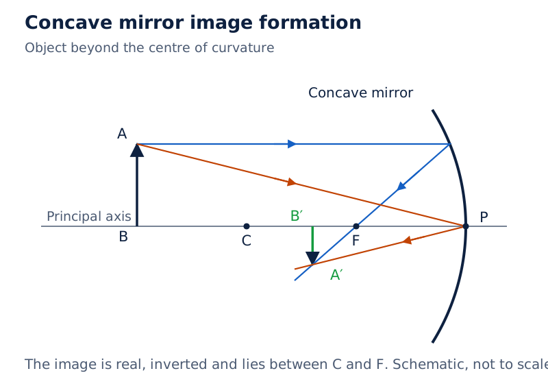
The object AB stands above the axis; its image A′B′ is inverted between the centre of curvature C and focus F. Rays from A reflect at the mirror, including its pole P, and meet at A′.
Drawn by One Young India.
Worked example 1. An object is 10 cm in front of a concave mirror of radius 15 cm. Find its image and magnification.
Formula: f = R/2; v = fu/(u − f); m = −v/u. Substitute: R = −15 cm, f = −7.5 cm, u = −10 cm.
Answer: v = (−7.5)(−10)/(−10 + 7.5) = −30 cm; m = −(−30)/(−10) = −3. The image is real, inverted and enlarged.
Worked example 2. Move the object to 5 cm in front of the same concave mirror of radius 15 cm.
Formula: v = fu/(u − f); m = −v/u. Substitute: f = −7.5 cm and u = −5 cm.
Answer: v = (−7.5)(−5)/(−5 + 7.5) = +15 cm; m = −15/(−5) = +3. The image is virtual, erect and enlarged, behind the mirror.
How does refraction at plane surfaces change the apparent position of objects?
The refractive index compares light speeds. Write n₁ and n₂ for the absolute indices of the incident and transmitted media. An absolute index compares the speed in vacuum with that in the medium. Relative index n₂₁ = n₂/n₁ describes medium 2 relative to medium 1.
Snell's law is n₁ sin i = n₂ sin r, where i and r are the angles of incidence and refraction. Equivalently, n₂₁ = sin i/sin r. The ratio remains constant for a fixed pair of media and a fixed wavelength. Indices are dimensionless.
Light bends towards the normal on entering an optically denser medium, meaning one with a higher refractive index. It bends away on entering an optically rarer medium. At normal incidence its direction does not change.
Note: Optical density is distinct from mass density, meaning mass per unit volume.
What happens through successive media?
Let n₃ be a third medium's index. The successive relative indices are n₂/n₁, n₃/n₂ and n₁/n₃. Their product is one because the factors cancel. Apply Snell's law separately at each boundary, measuring each angle from that boundary's own normal.
In a parallel-sided slab surrounded by the same medium, emergence is parallel to incidence but displaced sideways. Refraction at the two faces cancels the direction change.
Why does a submerged object appear raised?
For viewing from air nearly along the normal, let d be real depth and dₐ apparent depth, measured from the flat surface. With n the liquid's refractive index relative to air, dₐ = d/n. Apparent depth is smaller when n exceeds one.
When does total internal reflection occur, and how is it used?
Total internal reflection returns light completely into the denser medium when it reaches a rarer medium at a sufficiently large incidence angle. The critical angle, i꜀, is the incidence angle at which the refracted ray grazes the interface, making 90° with the normal.
With n₁ the denser-medium index and n₂ the rarer-medium index, sin i꜀ = n₂/n₁. Total internal reflection requires both n₁ > n₂ and i > i꜀. Equality gives grazing refraction, not the condition beyond the critical angle.
| Medium, relative to air | Refractive index | Critical angle in degrees |
|---|---|---|
| Water | 1.33 | 48.75 |
| Crown glass | 1.52 | 41.14 |
| Dense flint glass | 1.62 | 37.31 |
| Diamond | 2.42 | 24.41 |
How do reflecting prisms redirect rays?
A right-angled isosceles prism has angles 45°, 45° and 90°. Normal entry through a short face can produce 45° incidence at the hypotenuse and a 90° turn. Entry through the hypotenuse can produce two internal reflections and a 180° reversal, provided i꜀ < 45°.
What the figure shows
Totally reflecting prisms
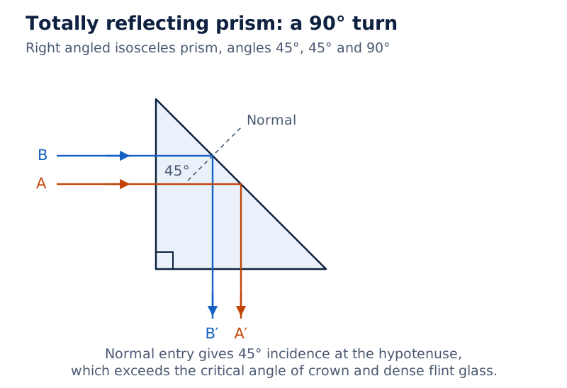
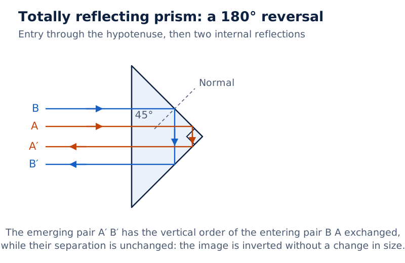
Two right-angled prism drawings show rays turned through 90° and 180°. A third drawing shows two rays exchanging their vertical order after passing through a prism, illustrating image inversion without a size change.
Drawn by One Young India.
For 30°-60°-90° prisms, find incidence from the face normal. Crown glass with critical angle 41.14° transmits at 30° internal incidence but totally reflects at 60°. A prism corner angle is not an incidence angle.
Draw and label
Paths in a 30°-60°-90° prism
Draw the triangle with its shortest face vertical and longest face inclined. Show normal entry through the shortest face giving 60° incidence at the longest face. Separately show normal entry through the other perpendicular face giving 30° incidence there. Mark normals and apply the critical-angle test.
How does an optical fibre guide light?
An optical fibre has a transparent core surrounded by cladding, a covering of lower refractive index. Light entering at a suitable angle repeatedly undergoes total internal reflection at their boundary and can travel along a bent fibre.
There is no appreciable loss in signal intensity from the successive total internal reflections. Absorption must also be very small; the materials need purification and special preparation. Fibres transmit communication signals as light and serve as light pipes for viewing internal organs.
What the figure shows
Light guided through a fibre
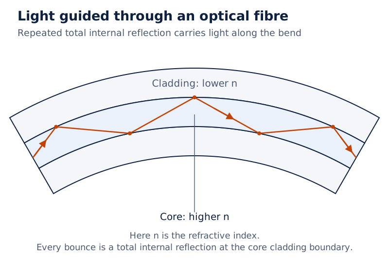
A zigzag ray crosses a curved inner region labelled high n and repeatedly reflects at its boundary with the outer low-n region. Here n denotes refractive index.
Drawn by One Young India.
How is the formula for refraction at a spherical surface derived?
A spherical refracting surface separates transparent media; its normals follow radii. Consider a surface convex towards the rarer incident medium, with an axial object producing a real image in the denser medium.
Derivation: a single convex refracting surface
Use a paraxial ray at height y. Let α, β and γ be the small positive angles made with the axis by the incident ray, the radius and the refracted ray, respectively. Take n₁ < n₂, u < 0, v > 0 and R > 0.
- Geometry gives incidence angle i = α + β and refraction angle r = β − γ.
- For small angles in radians, α ≈ y/(−u), β ≈ y/R and γ ≈ y/v. A radian measures angle as arc length divided by radius.
- Snell's law becomes n₁i ≈ n₂r. Substitution gives n₁[−y/u + y/R] = n₂[y/R − y/v].
- Cancel y and collect the object and image terms on the left.
n₂/v − n₁/u = (n₂ − n₁)/R. Distances are measured from the surface's pole. It requires paraxial rays and a small aperture, the transverse opening. Signs extend it to other spherical-surface cases.
What the figure shows
Refraction at a spherical interface
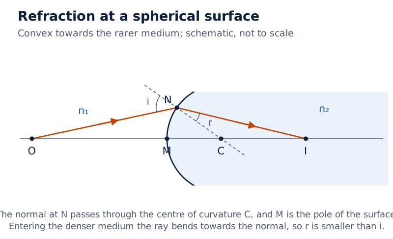
Object O lies in medium n₁ to the left of the convex surface. A ray reaches the surface at N and bends towards the normal through C, the centre of curvature, before meeting the axis at image I in medium n₂.
Drawn by One Young India.
Worked example 3. A point source in air of index 1 is 100 cm from a glass surface of index 1.5. The surface is convex towards the source and has radius 20 cm. Find the image distance.
Formula: n₂/v − n₁/u = (n₂ − n₁)/R. Substitute: 1.5/v − 1/(−100) = (1.5 − 1)/20.
Answer: 1.5/v = 0.025 − 0.010 = 0.015 cm⁻¹, so v = +100 cm. The real image lies inside the glass, along the incident-light direction.
How do the lens maker's formula and thin-lens formula follow?
A lens is a transparent medium bounded by two surfaces, at least one spherical. A thin lens has negligible thickness, allowing both refractions to be referred approximately to its optical centre.
Derivation: the lens maker's formula
Let nₗ be the lens index, nₘ the index of the surrounding medium on both sides, R₁ and R₂ the signed radii of its first and second surfaces, and v₁ the first surface's intermediate image distance. Consider a biconvex lens with R₁ > 0 and R₂ < 0.
- The first surface gives nₗ/v₁ − nₘ/u = (nₗ − nₘ)/R₁.
- The first image acts as the second surface's object. Neglecting lens thickness gives nₘ/v − nₗ/v₁ = (nₘ − nₗ)/R₂.
- Add the equations to eliminate v₁: nₘ(1/v − 1/u) = (nₗ − nₘ)(1/R₁ − 1/R₂).
- For an object at infinity, 1/u tends to zero and v = f. Divide by nₘ to obtain the focal-length relation.
1/f = (nₗ/nₘ − 1)(1/R₁ − 1/R₂). This is the lens maker's formula. Comparing it with the summed equation gives the thin-lens formula: 1/v − 1/u = 1/f.
How do lens shape and surrounding medium matter?
For a biconcave glass lens in air, R₁ is negative and R₂ positive, giving negative f. A plano-convex lens has one plane and one convex surface; the plane surface has zero reciprocal radius. The same formula applies with the appropriate signed curved radius.
A lens immersed in liquid requires the relative index nₗ/nₘ, rather than nₗ alone. If the two indices are equal, the reciprocal focal length is zero. The lens then has no converging or diverging effect.
For a thin lens, m = h′/h = v/u. Similar triangles formed by the undeviated central ray give this ratio. For a real object, a negative result indicates a real inverted image; a positive result indicates a virtual erect image.
Power, P, measures a lens's convergence or divergence: P = 1/f, with f in metres. The SI unit of lens power is dioptre (D), equivalent to m⁻¹. Converging lenses have positive power; diverging lenses have negative power.
Worked example 4. A double-convex lens in air of index 1 has surface radii of magnitudes 10 cm and 15 cm and focal length 12 cm. Find its material's index nₗ.
Formula: 1/f = (nₗ − 1)(1/R₁ − 1/R₂). Substitute: 1/12 = (nₗ − 1)[1/10 − 1/(−15)].
Answer: 1/12 cm⁻¹ = (nₗ − 1)/6 cm⁻¹, giving nₗ = 1.5, a dimensionless refractive index.
Worked example 5. A glass lens of index 1.5 has focal length 20 cm in air of index 1. Find its focal length fᵥ in water of index 1.33, with its shape unchanged.
Formula: fᵥ/f = (nₗ − 1)/(nₗ/nₘ − 1). Substitute: fᵥ/20 = 0.5/(1.5/1.33 − 1).
Answer: fᵥ ≈ +78.2 cm. The lens remains converging but bends rays less strongly in water.
How are combinations of lenses and mirrors analysed?
In an optical combination, rays pass successively through components. An intermediate image may be a real or virtual object. For a virtual object, incoming rays are already converging towards a point beyond the next component.
Derivation: two thin lenses in contact
Let f₁ and f₂ be the lenses' focal lengths, v₁ the first lens's image distance, and F the equivalent focal length. Treat their optical centres as coincident.
- For the first lens, 1/v₁ − 1/u = 1/f₁.
- For the second lens, 1/v − 1/v₁ = 1/f₂, since v₁ locates its object.
- Add to obtain 1/v − 1/u = 1/f₁ + 1/f₂. Compare this with the formula for a single equivalent lens.
1/F = 1/f₁ + 1/f₂. Thus P = P₁ + P₂, where P₁ and P₂ are the individual powers and P the combined power. Add signed powers, not focal lengths. The result requires thin lenses in contact.
Worked example 6. A convex lens of focal length 30 cm touches a concave lens of focal length 20 cm. Neglect their thicknesses. Find the combined focal length.
Formula: 1/F = 1/f₁ + 1/f₂. Substitute: 1/F = 1/30 + 1/(−20) = −1/60 cm⁻¹.
Answer: F = −60 cm. The combination is diverging because the concave lens contributes the larger power magnitude.
What changes when a mirror is included?
For a lens-and-mirror system, follow encounter order: lens refraction, mirror reflection, then return refraction if rays recross the lens. Measure each object distance from its component.
Use the lens equation for each refraction and the mirror equation for reflection. After reflection, the incident direction for a return lens passage is reversed; assign signs accordingly. Keep the same upward-positive convention for heights.
Let m₁, m₂ and m₃ denote the signed transverse magnifications of successive stages. Then m = m₁m₂m₃, because intermediate heights cancel in the ratios. Multiplying powers is incorrect, and adding lens powers does not analyse an arbitrary lens-and-mirror arrangement.
A useful limiting case places an object at a converging lens's front focus, with a plane mirror behind the lens perpendicular to its axis. The lens sends out parallel rays; the mirror returns them parallel; the return passage focuses them in the original focal plane.
How does a prism deviate light, and what is minimum deviation?
A prism has refracting plane faces inclined at prism angle A. Let i be incidence, e emergence, and r₁ and r₂ the internal angles, all measured from face normals. Deviation δ measures the change between initial and final ray directions.
Derivation: the minimum-deviation formula
Take the same surrounding medium on both sides of the prism. Let n be the prism index relative to that medium, and δₘ the minimum value of the deviation.
- The geometry of the prism and its normals gives r₁ + r₂ = A.
- The two deviations add: δ = (i − r₁) + (e − r₂) = i + e − A.
- At minimum deviation the path is symmetric: i = e and r₁ = r₂ = A/2. Hence i = (A + δₘ)/2.
- Substitute these angles into n = sin i/sin r₁.
n = sin[(A + δₘ)/2]/sin(A/2). In an equilateral prism at minimum deviation, the internal ray is parallel to the base. An equilateral triangular cross-section has all three angles equal.
What the figure shows
Refraction through a prism
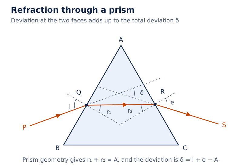
Ray PQ enters face AB at Q, travels inside to R on face AC, and emerges as RS. The face normals mark internal angles r₁ and r₂; the extended ray directions mark deviation δ.
Drawn by One Young India.
What does the incidence-deviation graph show?
As incidence increases, deviation falls to a minimum and then rises. In general, a deviation above the minimum corresponds to two incidence angles, related by reversing the ray path. At the minimum those two values coincide.
What the figure shows
Deviation against incidence
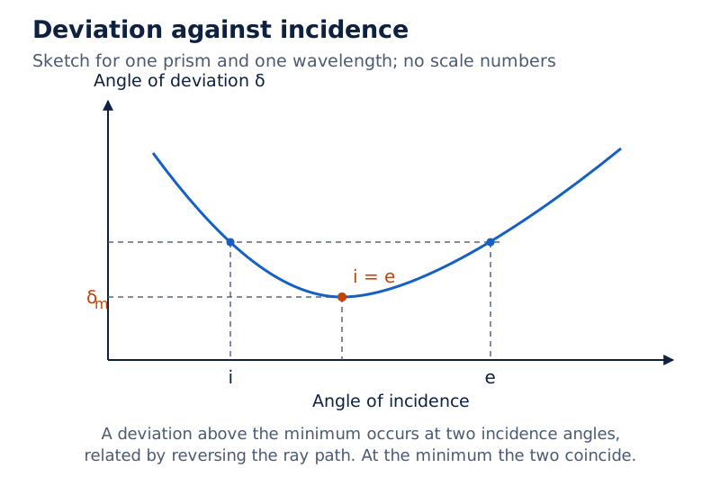
Incidence is on the horizontal axis and deviation on the vertical axis. The curve falls and rises, with i = e marked at its lowest point.
Drawn by One Young India.
For a thin prism, with small prism and ray angles expressed in radians, replacing sines by their small angles gives δ ≈ (n − 1)A. This approximation does not replace the full sine formula for a large prism angle.
How do dispersion and internal reflection produce a rainbow?
Dispersion is the splitting of light into its constituent colours. The coloured band is a spectrum. A glass prism bends different colours through different angles: red bends least and violet most. The colours emerge along distinct paths rather than being created by the prism.
The sequence is violet, indigo, blue, green, yellow, orange and red. You might not be able to see all the colours separately. A second identical inverted prism can recombine them into white light.
How are angular dispersion and dispersive power defined?
Angular dispersion, Δδ, is the difference between violet deviation δᵥ and red deviation δᵣ. For a thin prism in air, let nᵥ, nᵣ and nᵧ be its refractive indices for violet, red and yellow light respectively. Yellow provides the reference deviation δᵧ.
Δδ = δᵥ − δᵣ ≈ (nᵥ − nᵣ)A. The dispersive power, ω, is angular dispersion divided by the yellow reference deviation: ω = (nᵥ − nᵣ)/(nᵧ − 1). It is dimensionless and independent of prism angle within the small-angle approximation.
What happens inside a raindrop?
- Sunlight enters a water droplet and is refracted and dispersed.
- Light undergoes internal reflection at the back of the droplet.
- It is refracted again as it leaves the droplet.
- Different emerging colours reach the observer, producing a rainbow in the direction opposite to the Sun.
What the figure shows
Rainbow formation
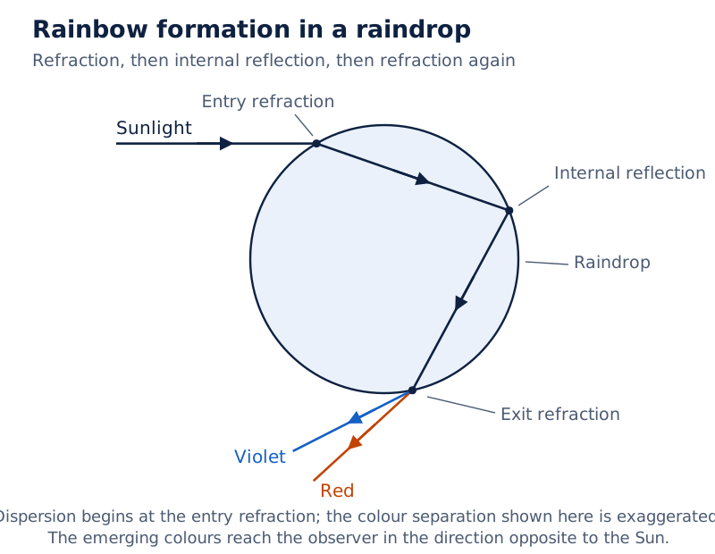
Sunlight enters the upper-left side of a circular raindrop. Coloured paths bend towards the back of the drop, reflect internally and emerge downwards to the left. The drawing distinguishes entry refraction, internal reflection and exit refraction.
Drawn by One Young India.
How does a simple microscope increase angular size?
A simple microscope is a converging lens of short focal length held close to the eye. With the object within its focal length it forms an erect, enlarged virtual image. With the object at its focus, emerging rays are parallel and the image is at infinity.
The least distance of distinct vision, D, is the nearest distance for clear viewing, about 25 cm for a normal eye. Here D is a distance symbol, distinct from the unit symbol for dioptre. A near-point image causes some strain; infinity is often considered most suitable for relaxed viewing.
Derivation: magnifying power at the near point and infinity
Magnifying power, M, compares the angular size seen through an instrument with the appropriate unaided angular size. For a microscope, use the object viewed unaided at D. Let α be this reference angle and β the angle seen through the lens.
- For object height h and small angles, α ≈ h/D. Put the eye close to the lens.
- Let s = −u be the positive object-to-lens distance. Then β ≈ h/s, so M = β/α = D/s.
- For a near-point image, v = −D. The lens equation gives −1/D + 1/s = 1/f, hence M = 1 + D/f.
- For an image at infinity the object lies at the focus: s = f. Therefore M = D/f.
M = 1 + D/f at the near point; M = D/f at infinity. Both are dimensionless. The relaxed-eye value is one less, but the difference is usually small.
What the figure shows
Simple microscope
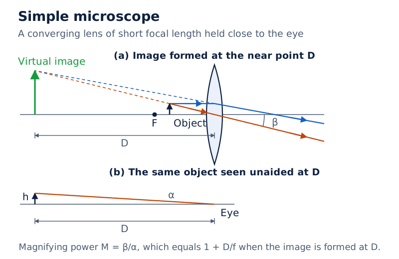
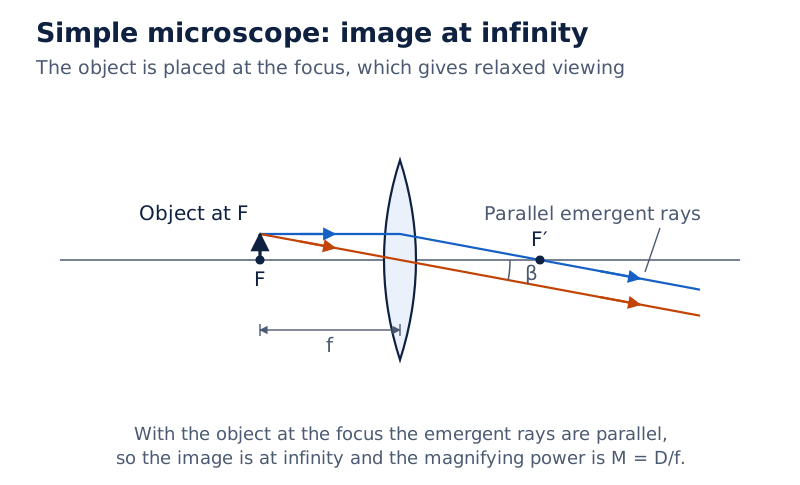
Panel (a) shows a convex lens producing a larger upright virtual image on the object side. Panel (b) shows unaided viewing at D. Panel (c) places the object near the focal point and shows a distant virtual image.
Drawn by One Young India.
How does a compound microscope magnify and resolve detail?
A compound microscope combines two converging systems. The objective, nearest the object, forms a real, inverted, enlarged intermediate image. The eyepiece, nearest the eye, acts as a simple microscope, giving an enlarged virtual final image inverted relative to the original object.
What the figure shows
Compound microscope
A small upright object AB is close to the objective. Rays form the inverted intermediate image A′B′ before the eyepiece. Backward extensions of the emerging rays locate the larger inverted virtual image A″B″ at near-point distance D from the eyepiece.
Derivation: magnifying power with the final image at D
Let fₒ and fₑ be objective and eyepiece focal lengths, uₒ and vₒ the objective's signed object and image distances, and h₁ the magnitude of the intermediate-image height. Let Mₒ be the objective's linear magnification magnitude and Mₑ the eyepiece's angular magnification.
- The objective gives Mₒ = h₁/h = |vₒ/uₒ|.
- For a near-point final image, the eyepiece gives Mₑ = 1 + D/fₑ, treating the intermediate image as its object.
- The angular size after the eyepiece is approximately Mₑh₁/D. Divide by the unaided reference h/D.
- The resulting magnifying-power magnitude is M = |vₒ/uₒ|(1 + D/fₑ).
M = |vₒ/uₒ|(1 + D/fₑ). For the usual approximation, let L be the distance between the objective's second focus and the eyepiece's first focus. With the intermediate image near that first eyepiece focus, Mₒ ≈ L/fₒ.
Thus the near-point result is approximately M ≈ (L/fₒ)(1 + D/fₑ). For the final image at infinity, use M = (L/fₒ)(D/fₑ) in the same approximation. These magnitudes become negative signed magnifications for the inverted image.
What limits useful magnification?
Resolving power is the ability to distinguish closely spaced details, not simply make an image larger. Diffraction, the spreading associated with a finite optical aperture, limits resolution even when geometrical imaging defects have been reduced.
Let λ be the light's vacuum wavelength, nₘ the index between specimen and objective, and a the half-angle of the light cone accepted by the objective. The numerical aperture is NA = nₘ sin a. For a circular aperture, minimum resolvable separation is approximately dₘᵢₙ = 0.61λ/NA.
Define resolving power as 1/dₘᵢₙ. Shorter wavelength and larger numerical aperture improve it. Simply increasing eyepiece magnification cannot separate unresolved detail. The microscope's advantage is large magnification of small objects; practical limitations include resolution, illumination and optical aberrations, meaning defects in image formation.
How do refracting and reflecting astronomical telescopes work?
An astronomical telescope increases the angular size of distant objects. Its objective has a long focal length and a larger aperture than its eyepiece. In a refracting telescope both are lenses. The objective forms a real inverted intermediate image, which the eyepiece magnifies.
How is magnifying power derived for normal adjustment?
Normal adjustment means the final image is at infinity. Let fₒ and fₑ now denote the telescope objective and eyepiece focal lengths. The objective image lies at the eyepiece's first focus. Let h₁ be its height magnitude, α the distant object's angle and β the final viewing angle.
Small-angle geometry gives α ≈ h₁/fₒ and β ≈ h₁/fₑ. Therefore the magnifying-power magnitude is M = fₒ/fₑ. The signed angular magnification is negative because the final image is inverted. Lens separation ℓ is ℓ = fₒ + fₑ.
What the figure shows
Refracting telescope
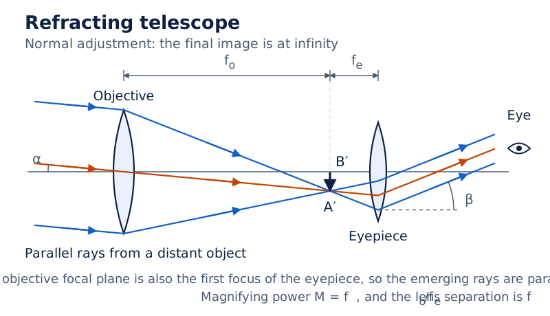
Parallel inclined rays enter the objective and form an inverted intermediate image. The eyepiece sends out parallel rays towards the eye. The marked distances fₒ and fₑ meet at the intermediate-image plane.
Drawn by One Young India.
Worked example 7. A telescope has objective focal length 144 cm and eyepiece focal length 6.0 cm. Find its magnifying power and lens separation in normal adjustment.
Formula: M = fₒ/fₑ; ℓ = fₒ + fₑ. Substitute: M = 144/6.0; ℓ = 144 + 6.0.
Answer: M = 24 and ℓ = 150 cm. The angular magnification magnitude is 24; the image is inverted.
What changes when the final image is at the near point?
Let s be the positive distance of the intermediate image from the eyepiece. With final image distance −D, its lens equation gives 1/s = 1/fₑ + 1/D. Thus s = fₑD/(D + fₑ).
Since α ≈ h₁/fₒ and β ≈ h₁/s, M = (fₒ/fₑ)(1 + fₑ/D). The separation becomes ℓ = fₒ + s, shorter than in normal adjustment. The final image remains virtual and inverted.
Diagram
Telescope adjusted to the near point
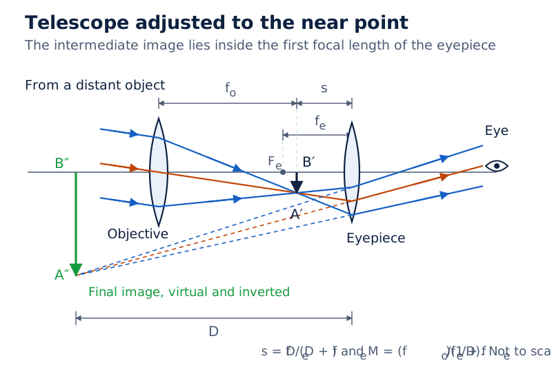
Draw an objective forming an inverted intermediate image. Place the eyepiece so that this image lies inside its first focal length. Show emerging divergent rays with backward extensions meeting at a virtual image a distance D from the eyepiece; label fₒ, fₑ and s.
Drawn by One Young India.
Why use a reflecting telescope?
A reflecting telescope uses a concave mirror as objective. It avoids chromatic aberration, the colour-dependent focusing defect of a lens. A mirror can be supported across its back; a large lens is heavy and must be supported around its edge.
What the figure shows
Cassegrain reflecting telescope
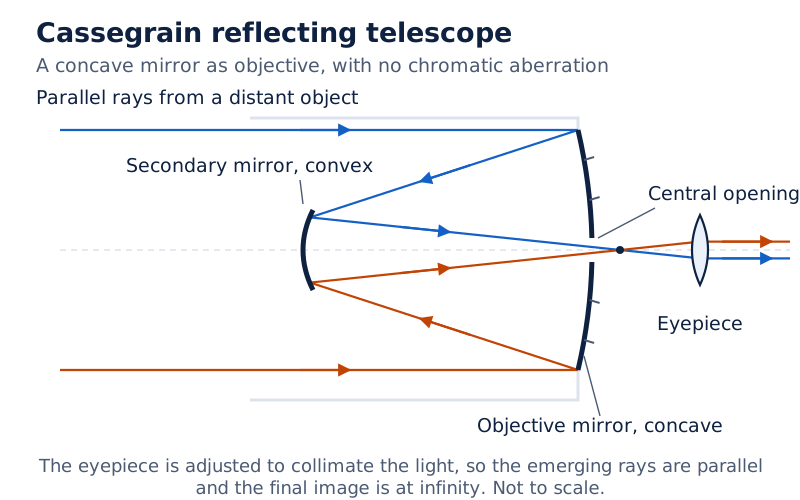
Parallel rays reach a large concave objective mirror, return towards a smaller convex secondary mirror, and are redirected through a central opening in the objective towards the eyepiece. For a final image at infinity, the eyepiece is adjusted to collimate the emerging light into parallel rays.
Drawn by One Young India.
The secondary mirror avoids placing the observer at the primary focus and gives a long focal length in a short tube, but intercepts some incoming light. Larger objectives gather more light and distinguish smaller angular separations.
| Instrument | Object and objective | Main use or limitation |
|---|---|---|
| Simple microscope | Nearby object; single short-focus converging lens | Enlarged viewing with limited magnification |
| Compound microscope | Small nearby object; short-focus objective | Much greater magnification; resolution and illumination limit detail |
| Refracting telescope | Distant object; long-focus lens objective | Astronomical viewing; large lenses are difficult to support and correct |
| Reflecting telescope | Distant object; concave mirror objective | No mirror chromatic aberration; secondary optics obstruct some incident light |
Glossary
- Paraxial ray — A ray close to the principal axis and making a small angle with it.
- Principal focus — The point where an axial parallel paraxial beam converges or appears to diverge after reflection or refraction.
- Virtual image — An image located where backward extensions of emerging rays meet, rather than the rays themselves.
- Refractive index — A ratio of light speeds specifying the optical behaviour of one medium relative to another.
- Critical angle — The incidence angle in the denser medium for which refraction into the rarer medium is at ninety degrees.
- Total internal reflection — Complete reflection back into the denser medium when incidence on a rarer medium exceeds the critical angle.
- Dioptre — The unit of lens power, equal to the reciprocal of one metre.
- Minimum deviation — The smallest angular change between incident and emerging rays for a given prism and wavelength.
- Dispersive power — The ratio of angular dispersion between chosen colours to the reference deviation through a thin prism.
- Magnifying power — The ratio of angular size through an instrument to angular size under the specified unaided viewing condition.
- Numerical aperture — The refractive index before a microscope objective multiplied by the sine of its accepted light-cone half-angle.
- Normal adjustment — An optical-instrument arrangement in which the final image is formed at infinity for relaxed viewing.
Common errors and misconceptions
- Misconception: Mirror and lens magnification have the same distance formula. Correct: With the stated Cartesian convention, a mirror gives −v/u and a thin lens gives v/u.
- Misconception: Every ray from a spherical mirror focuses exactly at half its radius. Correct: The relation is a paraxial approximation, requiring rays close to the axis.
- Misconception: Total internal reflection occurs at the critical angle. Correct: That angle gives grazing refraction; total internal reflection requires a larger incidence angle in the denser medium.
- Misconception: A lens's focal length is unchanged by immersion. Correct: The lens maker's formula uses the index relative to the surrounding medium.
- Misconception: Greater magnification guarantees more visible detail. Correct: Resolution limits distinguishable detail; merely enlarging unresolved images does not separate them.
- Misconception: A rainbow's internal reflection must be total. Correct: Its explanation requires refraction, dispersion, internal reflection and exit refraction, without assuming total internal reflection.
Exam-style questions with model answers
Q1. State the two conditions required for total internal reflection. [2 marks]
- Light must travel in an optically denser medium towards an interface with an optically rarer medium.
- The incidence angle, measured from the normal in the denser medium, must exceed the critical angle for that pair of media.
Q2. An object is 10 cm in front of a concave mirror of radius of curvature 15 cm. Calculate the image distance and magnification, and state the image's nature. [3 marks]
- Using the Cartesian convention with incident light positive, u = −10 cm and R = −15 cm. Therefore the focal length is f = R/2 = −7.5 cm.
- The mirror equation gives 1/v = 1/f − 1/u = −1/7.5 + 1/10 = −1/30 cm⁻¹. Thus v = −30 cm, in front of the mirror.
- Magnification m = −v/u = −3. The image is real, inverted and three times the object's height in magnitude.
Q3. A point source is 100 cm in front of a spherical glass surface convex towards it. The radius is 20 cm. Light travels from air of index 1 into glass of index 1.5. Calculate the paraxial image position and identify its nature. [4 marks]
- Taking incident light as positive, object distance u = −100 cm and radius R = +20 cm. The incident and transmitted indices are n₁ = 1 and n₂ = 1.5.
- Apply the spherical refraction equation, n₂/v − n₁/u = (n₂ − n₁)/R, with every distance measured from the surface pole.
- Substitution gives 1.5/v + 1/100 = 0.5/20, so 1.5/v = 0.015 cm⁻¹ and v = +100 cm.
- The image lies 100 cm inside the glass, in the incident-light direction. It is real because the refracted paraxial rays converge there.
Q4. Derive the thin-lens maker's formula for a biconvex lens of index nₗ surrounded on both sides by a medium of index nₘ. Its signed surface radii are R₁ and R₂. Assume paraxial rays and negligible lens thickness. [5 marks]
- Let u be object distance, v final image distance and v₁ the first surface's image distance. Use signed axial distances from the approximately coincident surface poles.
- For the first surface, the spherical refraction equation gives nₗ/v₁ − nₘ/u = (nₗ − nₘ)/R₁.
- The intermediate image becomes the second surface's object. Negligible thickness allows its object distance to be v₁, giving nₘ/v − nₗ/v₁ = (nₘ − nₗ)/R₂.
- Adding eliminates v₁: nₘ(1/v − 1/u) = (nₗ − nₘ)(1/R₁ − 1/R₂). This retains the effect of both refracting surfaces.
- For an object at infinity, 1/u tends to zero and v equals focal length f. Division by nₘ gives 1/f = (nₗ/nₘ − 1)(1/R₁ − 1/R₂).
Q5. A prism of angle A is surrounded by air of index 1. Derive its refractive index n in terms of its minimum deviation δₘ, and describe the incidence-deviation graph. [5 marks]
- Let i and e be incidence and emergence angles, and r₁ and r₂ the internal refraction angles, each measured from its face normal. Prism geometry gives r₁ + r₂ = A.
- The deviation δ adds the changes at the two faces: δ = (i − r₁) + (e − r₂) = i + e − A.
- At minimum deviation the path is symmetric. Therefore i = e and r₁ = r₂ = A/2, while i = (A + δₘ)/2.
- Snell's law at entry gives n = sin i/sin r₁. Substitution produces n = sin[(A + δₘ)/2]/sin(A/2).
- The graph falls to a minimum and then rises. In general, each deviation above the minimum corresponds to two incidence angles related by reversing the ray path.
Q6. A refracting astronomical telescope has objective focal length 144 cm and eyepiece focal length 6.0 cm. For a distant object in normal adjustment, explain the image arrangement, calculate magnifying power and lens separation, and state the final orientation. [4 marks]
- The distant object's real intermediate image forms at the objective's second focus. Position the eyepiece so that this image is also at its first focus, giving parallel emerging rays.
- The angular magnification magnitude is M = fₒ/fₑ = 144/6.0 = 24, where fₒ and fₑ are the objective and eyepiece focal lengths.
- The lens separation is ℓ = fₒ + fₑ = 144 + 6.0 = 150 cm.
- The final image is at infinity and inverted relative to the distant object. If orientation is included, the signed angular magnification is −24.
Key takeaways
- Choose and retain a sign convention; a negative distance identifies direction, while negative magnification identifies image inversion.
- Spherical-mirror and thin-lens equations use paraxial approximations, so their geometrical assumptions matter as much as correct substitution.
- Total internal reflection needs incidence from denser to rarer medium and an angle greater than the critical angle.
- The lens maker's formula includes the surrounding medium, while powers add algebraically for thin lenses in contact.
- At minimum prism deviation the path is symmetric, allowing refractive index to be found from prism angle and deviation.
- Microscopes enlarge nearby objects; astronomical telescopes enlarge the angular appearance of distant objects using different objective requirements.
- Distinguish image magnification from resolution: increasing size alone cannot reveal details already unresolved by the optical system.
Test yourself
Why can a real image exist without a screen?
The rays converge at the image position whether or not a screen is present. A screen makes that convergence visible by scattering light towards an observer.
When does apparent depth equal real depth divided by refractive index?
For viewing from air through a plane surface nearly along its normal, using the medium's refractive index relative to air.
Why is a fibre's cladding index lower than its core index?
This allows suitably directed light in the core to undergo total internal reflection at the core-cladding boundary.
What happens when a lens and its surrounding liquid have equal indices?
Its reciprocal focal length becomes zero, so it has no converging or diverging power in that liquid.
How do simple-microscope magnifying powers differ at D and infinity?
They are 1 + D/f and D/f respectively, with the eye close to the lens. Infinity gives more comfortable relaxed viewing.
Why can a reflecting telescope avoid chromatic aberration in its objective?
Its objective uses reflection at a mirror instead of the colour-dependent refraction of a lens.
Write about it
Turn a question from this chapter into a paper.
The Writing Studio has a structure guide, a rubric and citation tools for 15 formats, from essays to research papers. Drafting is free with an account. Learnacy Essential adds feedback from an AI writing coach and submission to The OYI Review.
Publication depends on review and is not guaranteed.