
Spherical mirrors | ICSE Class 9 Physics Notes
On this page

This note covers concave and convex spherical mirrors, their principal points, reflection rules, focal planes, ray diagrams, image characteristics, Cartesian signs, focal length, the mirror formula, magnification, numerical problems and uses of spherical mirrors.
What are spherical mirrors and how do their surfaces differ?
Reflection is the return of light from a surface. A spherical mirror has a reflecting surface that forms part of the surface of a sphere. A highly polished mirror reflects most of the light falling on it. Its curved reflecting surface may face inwards or outwards.
A concave mirror has its reflecting surface curved inwards, towards the centre of the sphere. A convex mirror has its reflecting surface curved outwards. Identify the reflecting face before deciding which kind of mirror a drawing represents.
An object is the body from which light reaches the mirror. Its image is the optical reproduction formed by reflected rays.
How does a shining spoon help?
The inward-curved surface of a shining spoon can be approximated to a concave mirror. Its outward-bulging surface can be approximated to a convex mirror. Moving the spoon away from the face helps reveal differences in the images produced by the two surfaces.
This comparison is an approximation, rather than a claim that every spoon has an exactly spherical surface. The important distinction is which curved face reflects the light. In schematic mirror drawings, the shaded side represents the non-reflecting back.
What the figure shows
Concave and convex reflecting surfaces
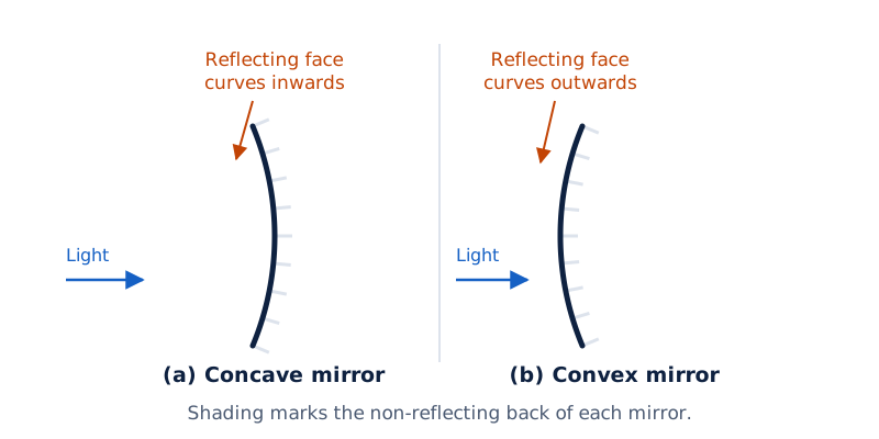
Two curved mirror outlines are shown. The concave surface curves inwards and the convex surface bulges outwards. Shading marks the non-reflecting side of each mirror.
Drawn by One Young India.
What does a ray represent?
A ray of light represents the path of light in the straight-line treatment used for mirror diagrams. A beam is a bundle of rays. Arrows on the rays show the direction in which light travels towards or away from the mirror.
What do pole, centre of curvature and principal axis mean?
The pole, represented by P, is the centre of a spherical mirror's reflecting surface. It lies on the mirror. The centre of curvature, represented by C, is the centre of the sphere of which that reflecting surface forms a part.
The centre of curvature is not a point on the reflecting surface. For a concave mirror it lies in front of the mirror; for a convex mirror it lies behind the mirror. This distinction determines where to place the labels in a ray diagram.
Which distances and lines describe the mirror?
The radius of curvature, represented by R, is the radius of the sphere forming the mirror surface. The distance from P to C, written PC, gives its magnitude. The straight line through P and C is the principal axis.
A normal is a line perpendicular to the reflecting surface at the point where light strikes it. For a spherical mirror, the radius through that point gives the normal. At the pole, the principal axis itself is the normal.
| Feature | Concave mirror | Convex mirror |
|---|---|---|
| Reflecting surface | Curved inwards | Curved outwards |
| Pole P | On the reflecting surface | On the reflecting surface |
| Centre of curvature C | In front of the mirror | Behind the mirror |
| Principal axis | Passes through P and C | Passes through P and C |
What is the aperture?
The aperture is the diameter of the reflecting surface. The spherical mirrors considered here have apertures much smaller than their radii of curvature. This condition matters when using a single principal focus and the usual relationship between focal length and radius of curvature.
What are the principal focus and focal length?
When rays parallel to the principal axis strike a concave mirror, the reflected rays meet on the axis. This point is its principal focus, represented by F. The rays converge, meaning that they come together at a point.
For a convex mirror, the reflected rays diverge, meaning that they spread apart. Their backward extensions appear to meet at a point on the principal axis behind the mirror. That point is the convex mirror's principal focus.
The focal length, represented by f, is the distance between the pole and the principal focus. Thus, the length from P to F gives its magnitude. The concave focus is in front of the mirror; the convex focus is behind it.
How are focal length and radius related?
Note: For spherical mirrors of small aperture, f = R/2, or equivalently R = 2f. The principal focus lies midway between the pole and the centre of curvature. The relation uses the same sign convention for both lengths: signs indicate their directions from the pole.
Derivation: Why is focal length half the radius of curvature?
Consider a paraxial ray parallel to the principal axis striking a concave mirror at . Let be the centre of curvature, the pole and the focus. Draw perpendicular to the axis.
- The radius is normal to the mirror at . If the angle of incidence is , the law of reflection gives and .
- Using the right triangles with perpendicular height , write and . Here the segment lengths are magnitudes.
- For paraxial rays, the angles are small. With angles in radians, and . Therefore, , giving .
- Since is near the pole, is very close to . Thus and : the focal length is half the radius of curvature in this approximation. For a concave mirror, both signed lengths are negative, preserving the relation.
Result: for a spherical mirror in the paraxial approximation.
The International System of Units is abbreviated to SI. The SI unit of focal length is the metre, symbol m. Radius of curvature and other lengths also use metres. A centimetre, symbol cm, is one hundredth of a metre.
What the figure shows
Principal foci of spherical mirrors
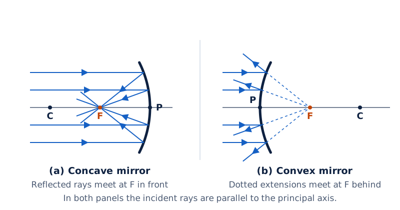
Parallel incident rays reach each mirror. The concave reflected rays meet at F in front of the mirror. The convex reflected rays spread out, with dotted backward extensions meeting at F behind it. P and C are marked on the axis.
Drawn by One Young India.
Which reflection rules determine the paths of useful rays?
The incident ray travels towards the mirror; the reflected ray travels away after striking it. Their meeting point on the surface is the point of incidence. The angle between the incident ray and the normal is the angle of incidence.
The angle of reflection is the angle between the reflected ray and that same normal. The two angles are equal. The incident ray, reflected ray and normal at the point of incidence lie in the same plane. These reflection laws apply to spherical surfaces.
Which rays are easiest to construct?
| Incident ray | Concave mirror: reflected path | Convex mirror: reflected path |
|---|---|---|
| Parallel to the principal axis | Passes through F | Appears to come from F |
| Through F, or directed towards F | A ray through F emerges parallel to the principal axis | A ray directed towards F emerges parallel to the principal axis |
| Through C, or directed towards C | A ray through C retraces its path | A ray directed towards C retraces its path |
| Obliquely towards P | Makes equal incident and reflected angles with the principal axis | Makes equal incident and reflected angles with the principal axis |
Obliquely means at an angle to the reference line. A ray through the centre of curvature retraces its path because it strikes along the normal. At other points, use the local radius as the normal rather than automatically using the principal axis.
What the figure shows
Focus, centre and pole rays
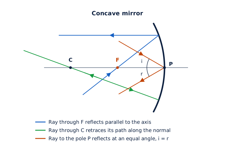
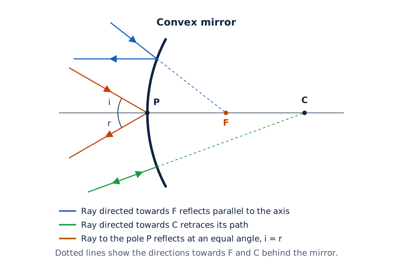
Paired concave and convex drawings show a focus ray reflected parallel to the axis, a centre-directed ray returning along its incoming path, and a pole ray reflected at an equal angle to the axis.
Drawn by One Young India.
How do parallel rays and rays through a focal-plane point behave?
The focal plane is the plane through the principal focus perpendicular to the principal axis. A plane is a flat surface extending in two dimensions; its cross-section appears as a line in the usual ray drawing.
The simple focusing rules concern paraxial rays: rays that strike near the pole and make small angles with the principal axis. Provided these conditions hold, a parallel beam inclined to the axis focuses at a point in the focal plane.
Must parallel rays pass through the principal focus?
Rays can be parallel to one another without being parallel to the principal axis. For a concave mirror, an inclined parallel beam converges at a point away from F in the focal plane. For a convex mirror, it appears to diverge from such a point.
The principal focus is the special focal-plane point for rays parallel to the principal axis. Distinguishing the axis direction from an inclined direction prevents the mistaken assumption that all parallel beams must reach the same point F.
What the figure shows
An inclined parallel beam
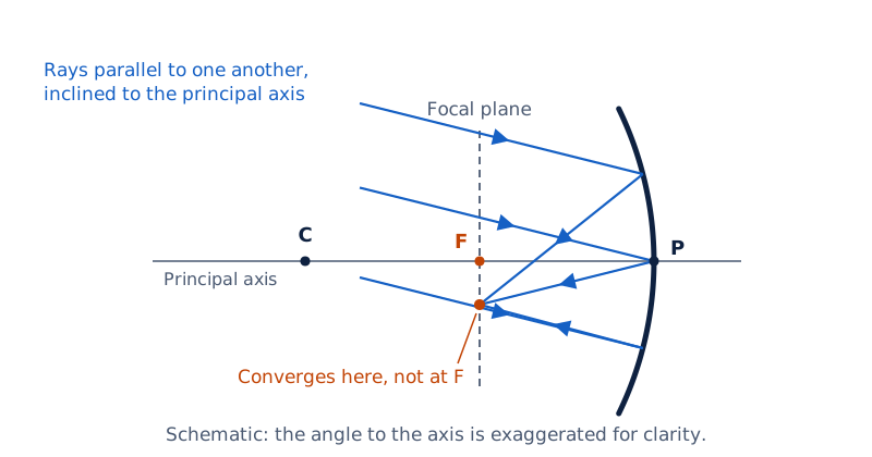
Parallel rays approach a concave mirror at an angle to its principal axis. Their reflected paths meet on the marked focal plane below F. The pole P and centre of curvature C are labelled on the principal axis.
Drawn by One Young India.
What happens when these paths are reversed?
The reversibility of a light path means that light can follow the same reflection path in the opposite direction. Rays from one point on a concave mirror's focal plane reflect as a parallel beam. An off-axis point, meaning a point away from the principal axis, produces an inclined beam.
For a convex mirror, incident rays directed towards one point on its focal plane behind the mirror emerge parallel after reflection. When the selected point is F, the emerging beam is parallel to the principal axis; an off-axis point gives an inclined beam.
How does a ray diagram locate an image?
A real image forms where reflected rays actually meet. A virtual image forms where the rays appear to meet when their paths are extended backwards.
A real image can be obtained on a screen at its position. A virtual image cannot be obtained on a screen there. For a virtual mirror image, the backward extensions behind the mirror describe apparent origins, rather than light actually travelling behind the reflecting surface.
How should the construction proceed?
- Draw the principal axis and the mirror, then label P, F and C in their correct positions.
- Represent the small linear object by an upright arrow with its base on the principal axis. Select its top as the object point to trace.
- Draw two useful rays from that same point and apply the appropriate reflection rules. Add arrows showing the direction of light.
- Locate the intersection of the reflected rays. If they diverge, extend them backwards with dotted lines to locate their apparent intersection.
- Draw the image arrow from the principal axis to the image point. State its position, orientation, relative size and whether it is real or virtual.
Many rays leave each object point. Drawing two does not mean that the object emits just two rays: two suitably chosen paths are enough to locate the image point clearly. Rays from different object points should not be combined to locate one image point.
How are image characteristics described?
An erect image has the same upright orientation as the object; an inverted image is upside down relative to it. An enlarged image is larger than the object, a diminished image is smaller, and a same-size image has equal height.
How does a concave mirror's image change with object position?
A concave mirror can form different kinds of images as the object moves relative to P, F and C. An object at infinity represents the limiting case of a very distant object whose arriving rays can be treated as parallel.
For the table below, C means the centre of curvature, F the principal focus and P the pole. Positions in front of the concave mirror are on the object's side. The size and nature descriptions belong to the corresponding object position.
| Position of the object | Position of the image | Size and nature of the image |
|---|---|---|
| At infinity | At the focus F | Highly diminished, point-sized; Real and inverted |
| Beyond C | Between F and C | Diminished; Real and inverted |
| At C | At C | Same size; Real and inverted |
| Between C and F | Beyond C | Enlarged; Real and inverted |
| At F | At infinity | Image would not be formed |
| Between P and F | Behind the mirror | Enlarged; Virtual and erect |
What makes the focus position special?
When the object is at F, reflected rays from an object point are parallel. They do not meet at a finite distance, so a screen at a finite distance cannot receive a sharp image. “At infinity” expresses this limiting image position.
What the figure shows
Concave image positions
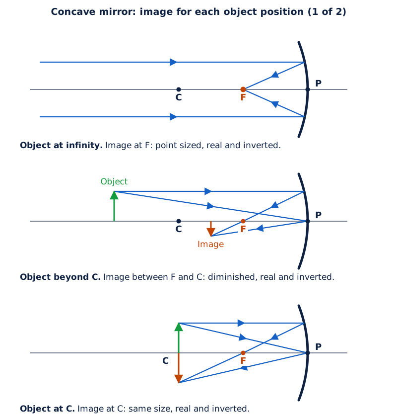
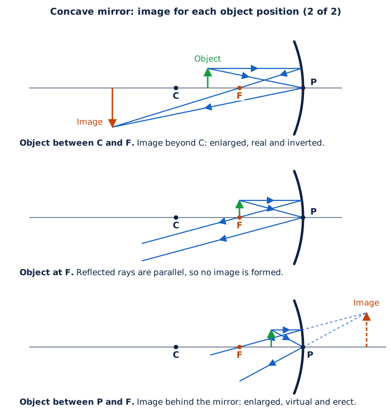
Six panels show the object at infinity, beyond C, at C, between C and F, at F, and between F and P. The last panel uses dotted backward extensions to locate an upright enlarged image behind the mirror.
Drawn by One Young India.
Which change produces a virtual image?
Moving the object inside the focal length, between P and F, produces the virtual, erect and enlarged image. A concave mirror therefore does not have one fixed image nature. The object position must be known before deciding whether its image is real or virtual.
What images does a convex mirror form?
For an object in front of a convex mirror, reflected rays diverge. Their backward extensions locate an image behind the mirror. The image is virtual and erect. At a finite object distance, it is diminished and lies between P and F.
The centre of curvature and principal focus are behind a convex mirror. Drawing them on the object's side would give the wrong ray paths. Remember that an incident ray directed towards F is reflected before it can reach that point behind the mirror.
How do the two object-position cases compare?
| Position of the object | Position of the image | Size of the image | Nature of the image |
|---|---|---|---|
| At infinity | At the focus F, behind the mirror | Highly diminished, point-sized | Virtual and erect |
| Between infinity and the pole P of the mirror | Between P and F, behind the mirror | Diminished | Virtual and erect |
What the figure shows
Convex mirror images
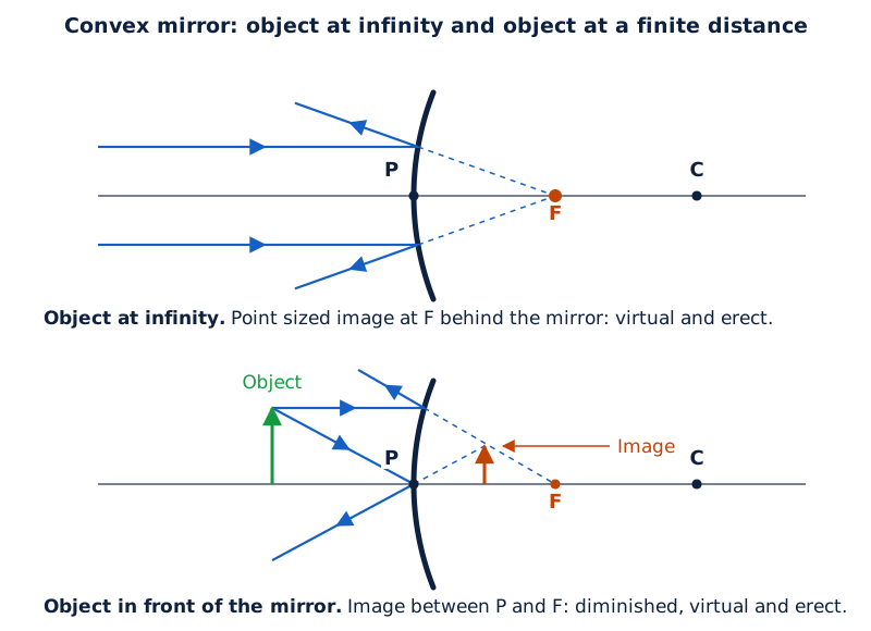
One panel shows incident rays from an object at infinity and a point image at F. The other shows an upright object and a smaller upright image between P and F, located by dotted backward extensions.
Drawn by One Young India.
A convex mirror can show the full-length image of a tall building or tree in a small mirror. Its diminished images and wider field of view, meaning the area visible through the mirror, help explain its use in vehicles.
Unlike the concave mirror, the convex mirror does not change from a real inverted image to a virtual erect image as an ordinary object is moved in front of it. Its image remains virtual, erect and diminished for finite object positions.
How are Cartesian signs and measurement units assigned?
The Cartesian sign convention assigns positive or negative signs to measured distances. Take the pole as the origin, or zero reference point, and the principal axis as the horizontal reference line. Place the object to the left, with incident light travelling from left to right.
The object distance, symbol u, is measured from the pole to the object. The image distance, symbol v, is measured from the pole to the image. These are signed distances, not merely positive separations.
What are the measurement rules?
- Measure all distances parallel to the principal axis from the pole, rather than from the focus or centre of curvature.
- Take distances to the right, in the incident-light direction, as positive. Take distances to the left as negative.
- Take heights measured perpendicular to and above the principal axis as positive.
- Take heights measured perpendicular to and below the principal axis as negative.
| Quantity | Sign in this arrangement | Reason |
|---|---|---|
| u for the object in front | Negative | Object lies left of P |
| Concave f and R | Negative | F and C lie left of P |
| Convex f and R | Positive | F and C lie right of P |
| v for a real mirror image | Negative | Image lies in front of the mirror |
| v for a virtual mirror image | Positive | Image lies behind the mirror |
Use the same length unit throughout a calculation. These quantities measure length, so their SI units agree. Converting every length consistently preserves both the answer and its sign.
| Measured quantity | Unit statement |
|---|---|
| Object distance u | The SI unit of object distance is the metre (m). |
| Image distance v | The SI unit of image distance is the metre (m). |
| Radius of curvature R | The SI unit of radius of curvature is the metre (m). |
| Object or image height | The SI unit of image height is the metre (m); object height uses the same unit. |
Centimetres may also be used consistently for the given numerical data. Do not mix a focal length in metres with an object distance in centimetres in the same substitution.
Note: Assign signs before substitution. A negative focal length identifies a concave mirror in this convention. It does not mean that a physical length is impossible; it identifies the direction of the focus from the pole.
How do the mirror formula and magnification describe an image?
The mirror formula relates image distance v, object distance u and focal length f. Use the signed quantities and a common length unit:
1/v + 1/u = 1/f
To find image distance, rearrange it as 1/v = 1/f − 1/u. A reciprocal means one divided by a quantity. This calculation first gives 1/v. Take its reciprocal to obtain v, then interpret the sign to state whether the image lies in front of or behind the mirror.
Derivation: How is the mirror equation obtained?
Consider an upright object and its real inverted image in a concave mirror, with and on the principal axis. A ray from , parallel to the axis, strikes at and reflects through .
- For paraxial rays, treat as perpendicular to the axis, with . The right triangles and are similar, so . These segment lengths are magnitudes.
- A ray from reflected at the pole gives equal angles and . Hence the right triangles and are similar, giving .
- The first ratio also gives . Equating the two expressions and using , obtain .
- Apply the Cartesian signs. The object, real image and focus are in front of the mirror, so , and . Substitution gives , or .
- Rearrange to . Dividing by gives .
Result: , using signed distances and the paraxial approximation.
How is magnification measured?
Magnification, usually represented by m, is the ratio of image height to object height. Let h represent signed object height and h′, read “h prime”, represent signed image height. The symbol m here denotes a ratio, not the metre unit.
m = h′/h and m = −v/u. Hence h′ = mh. Magnification has no unit because the equal length units in the ratio cancel. Use matching units for both heights or both distances.
What do the sign and size of magnification tell us?
For an upright object in front of the mirror, negative magnification indicates an inverted, real image; positive magnification indicates an erect, virtual image. The object height is usually positive because the object is usually placed above the principal axis.
The magnitude of magnification is its size without its sign. A magnitude greater than one means enlargement, less than one means diminution, and equal to one means the same size. The sign describes orientation separately from this size comparison.
Note: “Three times enlarged” does not by itself fix the sign of magnification. A three-times enlarged real image has negative magnification, while an erect virtual image enlarged by the same factor has positive magnification.
How are direct mirror numerical problems solved?
Start by identifying the mirror and assigning signs to the given distances. Choose the relation containing the required unknown, substitute with brackets around negative quantities, and retain units. Finish with the image's position and characteristics rather than leaving an uninterpreted signed number.
How are focal length and image distance found?
Worked example 1. Find the focal length of a convex mirror whose radius of curvature is 32 cm.
Formula: f = R/2. Substitute: R = +32 cm, since the centre of curvature is behind a convex mirror.
Answer: f = (+32 cm)/2 = +16 cm. Its principal focus is 16 cm behind the pole.
Worked example 2. A concave mirror produces a three-times enlarged real image of an object placed 10 cm in front of it. Find the image position.
Formula: m = −v/u; v = −mu. Substitute: m = −3 because the image is real and inverted, and u = −10 cm.
Answer: v = −(−3)(−10 cm) = −30 cm. The image is 30 cm in front of the mirror.
Worked example 3. A convex rear-view mirror has radius of curvature 3.00 m. A bus is 5.00 m in front of it. Find the image position, nature and size relative to the bus.
Formula: f = R/2; m = −v/u; 1/v = 1/f − 1/u. Substitute: R = +3.00 m, f = +1.50 m and u = −5.00 m.
Answer: 1/v = 1/1.50 + 1/5.00, giving v = +1.15 m, rounded. Then m = −1.15/(−5.00) = +0.23. The image is behind the mirror, virtual, erect and 0.23 times the bus's size. Its actual height cannot be calculated without the bus's height.
How are screen position and image height found?
The notation cm⁻¹ means reciprocal centimetres. It occurs in the intermediate reciprocal-distance calculation; the final distance has the unit centimetres. A negative image height indicates inversion, while the physical height is its magnitude.
Worked example 4. An object 4.0 cm high is 25.0 cm in front of a concave mirror of focal length 15.0 cm. Find the screen position for a sharp image, its nature and its height.
Formula: m = −v/u; h′ = mh; 1/v = 1/f − 1/u. Substitute: h = +4.0 cm, u = −25.0 cm and f = −15.0 cm.
Answer: 1/v = −1/15.0 + 1/25.0 = −2/75.0 cm⁻¹, so v = −37.5 cm. Place the screen 37.5 cm in front of the mirror. Magnification is −1.5 and h′ = −1.5 × 4.0 = −6.0 cm. The image is real, inverted and enlarged.
Worked example 5. An object is 10 cm in front of a convex mirror of focal length 15 cm. Find the position and nature of its image.
Formula: 1/v = 1/f − 1/u. Substitute: f = +15 cm and u = −10 cm.
Answer: 1/v = 1/15 + 1/10 = 1/6 cm⁻¹, so v = +6 cm. The image is 6 cm behind the mirror. It is virtual, erect and diminished, between the pole and focus.
Worked example 6. An object 7.0 cm high is 27 cm in front of a concave mirror of focal length 18 cm. Find the screen position, image height and image nature.
Formula: m = −v/u; h′ = mh; 1/v = 1/f − 1/u. Substitute: h = +7.0 cm, u = −27 cm and f = −18 cm.
Answer: 1/v = −1/18 + 1/27 = −1/54 cm⁻¹, giving v = −54 cm. Place the screen 54 cm in front of the mirror. Then m = −2 and h′ = −14.0 cm. The image is real, inverted and enlarged.
Why are concave and convex mirrors used for different purposes?
Choose a spherical mirror by the required effect: concentrating light, producing a parallel beam, enlarging a nearby object's image, or viewing a wide area. The useful property follows from the same ray rules used to construct images.
Where are concave mirrors useful?
Concave mirrors are commonly used in torches, searchlights and vehicle headlights to obtain powerful parallel beams. Light from a source at the focus reflects parallel to the principal axis. This is the focus-ray rule applied to a source of light.
Concave mirrors are often used as shaving mirrors to give a larger image of the face. Dentists use them to see large images of teeth. The erect enlarged image corresponds to an object between the pole and principal focus.
Large concave mirrors concentrate sunlight to produce heat in solar furnaces. The focusing effect brings incoming sunlight together. Concentrating light and enlarging a nearby object's image are different uses of the same kind of reflecting surface.
Why use convex mirrors in vehicles?
Convex mirrors are commonly used as rear-view or wing mirrors. They give an erect, diminished image and have a wider field of view because they curve outwards. A driver can therefore view a larger area than with a plane mirror.
An enlarged image alone would not fulfil the same purpose: seeing a larger area behind the vehicle is useful. The convex mirror combines this broader view with upright images. Its virtual image remains behind the mirror and is located by backward extensions of reflected rays.
Glossary
- Spherical mirror — A mirror whose reflecting surface forms part of the surface of a sphere.
- Concave mirror — A spherical mirror with its reflecting surface curved inwards towards the sphere's centre.
- Convex mirror — A spherical mirror whose reflecting surface curves outwards from the sphere's centre.
- Pole — The central point of a spherical mirror's reflecting surface, used as the distance reference.
- Centre of curvature — The centre of the sphere of which the reflecting surface forms a part.
- Radius of curvature — The radius of the sphere forming the spherical mirror's reflecting surface.
- Principal axis — The straight line passing through a spherical mirror's pole and centre of curvature.
- Principal focus — The axial point where initially axis-parallel rays meet or appear to originate after reflection.
- Focal length — The distance between the pole and the principal focus of a spherical mirror.
- Aperture — The diameter of the reflecting surface of a spherical mirror.
- Focal plane — The plane through the principal focus and perpendicular to the principal axis.
- Real image — An image formed at a position where the reflected rays actually meet.
- Virtual image — An image located where reflected rays appear to meet when extended backwards.
- Magnification — The ratio of signed image height to signed object height, expressing relative image size and orientation.
- Paraxial rays — Rays incident near the pole and making small angles with the principal axis.
Common errors and misconceptions
- Misconception: The pole and centre of curvature are the same point. Correct: The pole lies on the reflecting surface; the centre of curvature is the centre of the sphere forming that surface.
- Misconception: Every concave-mirror image is real. Correct: An object between the pole and focus produces a virtual, erect and enlarged image behind the mirror.
- Misconception: Any parallel beam must focus at F. Correct: An inclined parallel paraxial beam focuses, or appears to originate, at an off-axis point in the focal plane.
- Misconception: Dotted lines behind a mirror show actual reflected light. Correct: These are backward extensions locating the apparent origin of rays and hence the virtual image.
- Misconception: Every distance supplied in a numerical problem is positive. Correct: Assign Cartesian signs from the pole before substituting; an object in front has negative object distance in the stated arrangement.
- Misconception: Negative magnification means a smaller image. Correct: Its sign describes orientation. Its magnitude, compared with one, determines whether the image is enlarged or diminished.
- Misconception: An object exactly at a concave mirror's focus gives a sharp image on a nearby screen. Correct: Reflected rays are parallel, so no sharp image forms at a finite screen distance.
- Misconception: Relative image size gives its height without any object-height data. Correct: Magnification gives a ratio; calculating an actual image height also requires the object height.
Exam-style questions with model answers
Q1. Distinguish between the pole and centre of curvature of a spherical mirror. [2 marks]
- The pole is the centre of the reflecting surface and lies on the mirror.
- The centre of curvature is the centre of the sphere forming that surface; it does not lie on the reflecting surface.
Q2. A convex mirror has a radius of curvature of 32 cm. Calculate its signed focal length using the Cartesian convention, with incident light travelling from left to right. [2 marks]
- The centre of curvature is behind the convex mirror, so the signed radius is R = +32 cm.
- Using f = R/2, the focal length is +16 cm, locating the focus 16 cm behind the pole.
Q3. An upright small object is between the pole and principal focus of a concave mirror. Explain how two rays locate the image and state its position, nature, orientation and relative size. [3 marks]
- Draw a ray from the object's top parallel to the principal axis; after reflection it passes through the principal focus. Draw another ray from the same top point to the pole and reflect it at an equal angle to the axis.
- Extend these diverging reflected rays backwards. Their extensions meet behind the mirror, locating a virtual image.
- The image is erect and enlarged relative to the object, rather than an inverted image in front of the mirror.
Q4. Explain the focal plane and the paths of an inclined parallel paraxial beam incident on a concave mirror. Then describe the reversed path from the same focal-plane point. [3 marks]
- The focal plane passes through the principal focus and is perpendicular to the principal axis. Paraxial rays strike near the pole and make small angles with the principal axis.
- An inclined beam whose rays are parallel to one another converges after reflection at an off-axis point in this focal plane, rather than at the principal focus.
- Reversing these paths, rays originating at that same focal-plane point reflect as a parallel beam inclined to the principal axis.
Q5. A concave mirror forms a three-times enlarged real image of an upright object 10 cm in front of it. Using the Cartesian convention with light incident from the left, find the signed magnification and image position, and explain the sign of the answer. [3 marks]
- A real image of this upright object is inverted, so its three-times enlargement gives magnification m = −3. The object is in front of the pole, giving object distance u = −10 cm.
- Use m = −v/u, where v is the image distance. Therefore v = −mu = −(−3)(−10 cm) = −30 cm.
- The negative image distance places the image in front of the mirror, 30 cm from its pole.
Q6. An upright object 4.0 cm high is 25.0 cm in front of a concave mirror of focal length 15.0 cm. Using the Cartesian convention with light incident from the left, calculate the screen position, magnification and signed image height, and state the image's nature and relative size. [5 marks]
- Take the signed object height h = +4.0 cm, object distance u = −25.0 cm and focal length f = −15.0 cm, because the object and focus lie in front of the pole.
- Using 1/v = 1/f − 1/u gives 1/v = −1/15.0 + 1/25.0 = −2/75.0 cm⁻¹, hence image distance v = −37.5 cm.
- Place the screen 37.5 cm in front of the mirror. The negative image distance identifies the real image on the object's side.
- Magnification is m = −v/u = −(−37.5)/(−25.0) = −1.5. Its negative sign indicates that the image is inverted.
- The signed image height is h′ = mh = −1.5 × 4.0 = −6.0 cm. Its height is 6.0 cm, so it is enlarged.
Q7. A bus is 5.00 m in front of a convex rear-view mirror of radius of curvature 3.00 m. Using the Cartesian convention with incident light from the left, find the focal length, image position, magnification and image characteristics. Explain why this mirror is useful for rear viewing. [5 marks]
- The convex mirror has signed radius R = +3.00 m, so its focal length is f = R/2 = +1.50 m. The bus gives object distance u = −5.00 m.
- The mirror formula gives 1/v = 1/1.50 − 1/(−5.00). Thus image distance v = +1.15 m, rounded, placing the image behind the mirror.
- Magnification is m = −v/u = −1.15/(−5.00) = +0.23. This expresses the image height as 0.23 times the bus's height.
- The positive magnification indicates an erect virtual image; its magnitude below one indicates diminution. No actual bus height is supplied, so an absolute image height is not determined.
- The convex surface provides a wider field of view and upright images, enabling the driver to see a larger area of traffic behind the vehicle.
Q8. Explain one use of a concave mirror for producing a parallel beam and one use of a convex mirror in a vehicle. [2 marks]
- A concave mirror is used in a headlight to reflect light from a source at its focus into a powerful parallel beam.
- A convex rear-view mirror gives erect, diminished images and a wider field of view, helping the driver see traffic behind.
Key takeaways
- Concave mirrors reflect from an inward-curved surface; convex mirrors reflect from an outward-curved surface.
- The pole lies on the mirror, while the centre of curvature is the centre of the sphere forming its surface.
- For spherical mirrors of small aperture, focal length is half the radius of curvature.
- Inclined parallel paraxial rays focus, or appear to originate, at an off-axis point in the focal plane.
- A concave mirror's image depends on object position; between pole and focus, the image is virtual, erect and enlarged.
- A convex mirror forms virtual, erect, diminished images of objects in front of it and provides a wider field of view.
- Measure signed distances from the pole and use consistent units before substituting in the mirror formula.
- Magnification's sign describes image orientation, while its magnitude compares image height with object height.
Test yourself
Where is the centre of curvature of a convex mirror?
It lies behind the mirror, on the principal axis through the pole.
What happens to a ray directed towards a convex mirror's principal focus?
It reflects from the mirror and emerges parallel to the principal axis.
Why does a ray through a concave mirror's centre of curvature retrace its path?
It strikes the mirror along the normal, which is the radius through the point of incidence.
What happens to rays from one point of a concave mirror's focal plane?
Within the paraxial treatment, they reflect as a parallel beam. An off-axis point gives an inclined beam.
Where must an object be placed to obtain a same-size real image in a concave mirror?
Place it at the centre of curvature; the inverted image also forms there.
What is special about an object exactly at a concave mirror's focus?
Its reflected rays are parallel, so they do not form a sharp image at a finite screen distance.
What does negative image height mean for an upright object?
The image extends below the principal axis and is inverted relative to the object.
Why can a magnification ratio alone not give an absolute image height?
The ratio compares image and object heights; the object height is also needed to calculate the image height.
Write about it
Turn a question from this chapter into a paper.
The Writing Studio has a structure guide, a rubric and citation tools for 15 formats, from essays to research papers. Drafting is free with an account. Learnacy Essential adds feedback from an AI writing coach and submission to The OYI Review.
Publication depends on review and is not guaranteed.