
Electricity and Magnetism | ICSE Class 9 Physics Notes
On this page
This note covers electric charge, free electrons, conductors and insulators, simple circuits, electric current, potential difference, resistance, Ohm’s law, circuit symbols, electrical measurements, induced magnetism, magnetic field lines, Earth’s magnetic field and neutral points.
What are electric charge and free electrons?
Electric charge is a property of matter associated with electric forces. An electron is a negatively charged particle in an atom; a proton is a positively charged particle. Positive and negative charges balance in an electrically neutral body.
Adding or removing electrons can upset this balance. A body that gains electrons becomes negatively charged, whereas a body that loses electrons becomes positively charged. Losing electrons does not mean that positive particles have been added to the body.
What makes an electron free?
In metals, some electrons are practically free to move within the material rather than remaining attached to individual atoms. These are called free electrons. Their movement can carry charge through a metal. Electric current means the rate at which electric charge flows.
Without an applied electric influence, electrons still undergo random motion. This motion has no preferred direction and gives no net current. Establishing a potential difference, meaning the work done per unit charge moved between two points, produces directed charge flow in a conducting path.
What does quantisation of charge mean?
Quantisation of charge means that the charge of a body occurs in integral multiples of the elementary charge. Let q denote the body’s net charge, n a positive or negative integer or zero, and e the magnitude of an electron’s charge.
q = ne
The SI, or International System of Units, unit of electric charge is the coulomb, symbol C. Using the rounded value, e = 1.6 × 10⁻¹⁹ C. An electron carries −e and a proton carries +e. The sign distinguishes the two kinds of charge.
Because this elementary charge is extremely small, charge can appear continuous when dealing with large collections of charged particles. That appearance does not remove its quantised nature. Nearly 6 × 10¹⁸ electrons together carry a charge whose magnitude is one coulomb.
Note: “Free” describes an electron’s ability to move through a material. It does not mean that the electron has no charge or meets no opposition while moving through a conductor.
How do conductors, insulators and other electrical materials differ?
A conductor allows electric charge to move through it readily. An insulator offers high opposition to the passage of electricity. This opposition is called resistance. Copper is a conductor; glass, plastic and porcelain are examples of insulators.
Most non-metals such as glass, porcelain, plastic, nylon and wood offer high resistance. The word most matters: a statement about most non-metals must not be changed into a statement about every non-metal. Classification depends on the electrical behaviour of the material.
Why should comparisons use components of the same size?
For components of a given size, low resistance indicates a good conductor. A component of identical size with higher resistance is a poor or bad conductor. An insulator of the same size offers even higher resistance. Comparing similar dimensions keeps the comparison meaningful.
| Material category | Electrical behaviour |
|---|---|
| Good conductor | Offers low resistance to charge flow for a component of a given size. |
| Poor or bad conductor | Offers higher resistance than a good conductor of identical size. |
| Insulator | Offers even higher resistance to the passage of electricity. |
| Semiconductor | Has electrical behaviour intermediate between conductors and insulators. |
| Superconductor | Exhibits zero electrical resistance in its superconducting state. |
What are semiconductors and superconductors?
A semiconductor has a resistance to charge movement intermediate between that of conductors and insulators. Silicon and germanium are examples. This category is distinct from an ordinary good conductor and from an insulator.
A superconductor exhibits perfect electrical conduction, meaning zero electrical resistance, under the conditions needed for superconductivity. Certain materials show this behaviour when cooled to very low temperatures. A metal that conducts well at ordinary temperature is not thereby a superconductor.
These categories concern electrical behaviour. In a metallic conductor, free electrons carry current, but their motion is opposed by resistance. The existence of free electrons therefore does not justify assuming that an ordinary metal has zero resistance.
How does a cell make a simple electric circuit work?
An electric cell is a source that uses stored chemical energy to maintain a potential difference between its terminals. A terminal is a connection point. A cell has positive and negative terminals, marked + and − respectively.
An electric circuit provides a continuous conducting path for current. A simple circuit contains a cell, connecting wires, a bulb and a key, or switch, which makes or breaks the path. The bulb’s filament is its thin conducting wire.
What changes when the key is opened or closed?
- Connect the cell, bulb and key with conducting wires to form a circuit.
- Close the key so that the conducting path is complete.
- Current passes through the complete circuit and the bulb glows.
- Open the key to break the conducting path; current stops and the bulb no longer glows.
| Feature | Closed circuit | Open circuit |
|---|---|---|
| Conducting path | Complete | Broken somewhere |
| Current in the simple bulb circuit | Flows when supplied by the cell | Does not flow |
| Bulb | Glows in the working circuit | Does not glow |
The chemical action of a cell produces a potential difference even when no current is drawn from it. Thus an open key stops current around the circuit, but it does not mean that the cell’s terminals have lost their potential difference.
What are direct-current sources and accumulators?
Direct current, abbreviated DC, flows in one direction. Cells supply direct current to a connected circuit. A battery supplies electrical energy using cells. The cell provides the driving potential difference; electrons already present in the metal carry the current.
An accumulator is a rechargeable, or secondary, cell. A secondary cell can be recharged after use and used again. The lead storage battery is an example commonly used in automobiles and inverters. Both cells and accumulators serve as sources for suitable circuits.
What the figure shows
Simple electric circuit
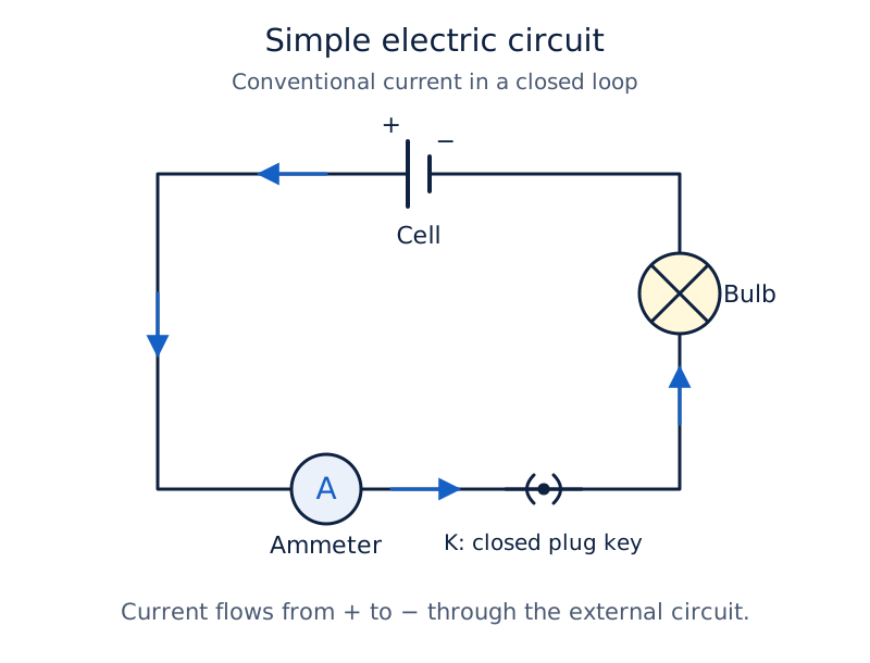
The drawing shows a source, bulb, ammeter and plug key connected in one loop. Arrows show current around the loop. The letter A inside a circle identifies the ammeter, an instrument for measuring current, and K labels the key.
Drawn by One Young India.
How are current, charge and time related?
Definition: Electric current is the rate of flow of electric charge through a cross-section of a conductor. A cross-section is an imagined cut across the wire through which passing charge is counted.
Let Q represent the amount of charge passing through the cross-section, t the time taken and I the current. For steady current, meaning current that does not change with time, the relationship is:
I = Q/t
The SI unit of current is the ampere, symbol A. One ampere means that one coulomb of charge passes through the cross-section in one second. The symbol s stands for second.
1 A = 1 C/1 s. Equivalently, 1 C = 1 A × 1 s. The rearrangements for charge and time are Q = It and t = Q/I. Use coulombs, amperes and seconds together in these relationships.
Which direction does current take?
Conventional current takes the direction in which positive charge would flow. In the external circuit, meaning the circuit outside the cell, this is from the positive terminal towards the negative terminal. Electron flow in the metallic wires is in the opposite direction.
Thus the direction of electron movement and conventional current must be distinguished. An arrow labelled current normally represents conventional current. Negatively charged electrons move from the negative terminal towards the positive terminal through the external metallic circuit.
How is a charge calculation set out?
Worked example 1. A bulb filament draws 0.5 A for 10 minutes. Find the charge passing through the circuit. Use 1 minute = 60 seconds.
Given: I = 0.5 A. Let tₘ denote the time in minutes, so tₘ = 10.
Formula: t = 60tₘ in seconds; Q = It.
Substitute: t = 10 × 60 = 600 s; Q = 0.5 × 600.
Answer: 300 C of charge passes through the circuit during 600 s.
A milliampere, written mA, is 10⁻³ A; a microampere, written µA, is 10⁻⁶ A. These units describe small currents. Convert a current to amperes before substituting into a calculation that uses coulombs and seconds.
What does potential difference measure?
Potential difference between two points measures the work done per unit charge moved between them. Here work means energy transferred in moving the charge. Current measures how rapidly charge passes; potential difference measures energy transferred for each unit of charge.
Let V denote potential difference, W the work done and Q the charge moved. The defining relationship is V = W/Q. The SI unit of work is the joule, symbol J.
The SI unit of potential difference is the volt, whose unit symbol is also V. In a formula V represents the quantity; after a numerical value V means volts. One volt corresponds to one joule of work for one coulomb of charge.
1 V = 1 J/1 C
Why is a cell needed?
Charges do not develop a directed flow through a copper wire merely because the wire contains free electrons. A cell maintains a potential difference across the connected conducting path. Its stored chemical energy supplies the energy needed to maintain current.
A water-flow comparison can help: a difference in pressure can cause water to flow through a tube. In a metallic circuit the relevant driving difference is electrical potential difference. Gravity does not provide the driving cause of electron flow in this comparison.
Worked example 2. How much work is done in moving 2 C between points at a potential difference of 12 V?
Given: Q = 2 C; V = 12 V. Formula: W = VQ.
Substitute: W = 12 × 2. Answer: 24 J.
Worked example 3. How much energy is transferred to each coulomb of charge passing through a 6 V battery? Here “each coulomb” means Q = 1 C.
Given: V = 6 V; Q = 1 C. Formula: W = VQ.
Substitute: W = 6 × 1. Answer: 6 J.
W = VQ gives the total work for the specified charge. The result depends on both the potential difference and the amount of charge transferred. Do not give a work answer in volts: volts express work per coulomb, while joules express work.
How are circuit symbols and measuring instruments used?
A circuit diagram represents components using conventional symbols joined by lines for conducting wires. It shows electrical connections without needing a picture of each physical object. Read both the component symbols and the paths connecting them.
A series connection places components one after another in the same current path. A parallel connection joins components across the same two points. These terms explain how current and potential-difference meters must be connected.
Which instrument measures which quantity?
| Instrument | Purpose | Connection or observation |
|---|---|---|
| Ammeter | Measures electric current | Connected in series in the path carrying the current |
| Voltmeter | Measures potential difference | Connected in parallel across the two points being compared |
| Galvanometer | Detects electric current | Its needle deflection indicates the presence of current |
The ammeter measures the current passing through its path. The voltmeter compares the electric potentials of two points. A galvanometer detects current. Knowing the purpose of each instrument prevents an ammeter from being mistaken for a potential-difference meter.
How can the common symbols be recognised?
A resistor is a component offering appreciable resistance. A rheostat is a variable resistance used to regulate current. A resistance wire or a resistance box can also provide resistance in a circuit; a resistance box offers selectable resistance values.
| Component or connection | Symbol to recognise |
|---|---|
| Cell | Unequal parallel lines, with the longer line at the positive terminal |
| Battery | A succession of cell symbols |
| Open plug key | Separated curved contacts without the filled central dot |
| Closed plug key | Curved contacts with the filled central dot |
| Wire joint | Meeting wires with a filled dot at the junction |
| Wires crossing without joining | One wire drawn with a bridge over the other |
| Resistor | A zigzag line between connecting wires |
| Rheostat | A resistance symbol with an arrow indicating adjustment |
| Ammeter and voltmeter | A circle containing A or V respectively |
Trace a diagram from one terminal of the source through the connected components to the other terminal. Notice whether a crossing is a joint or simply an overlap on the page. The distinction changes which components are electrically connected.
What is resistance, and what does Ohm’s law state?
Resistance is the property of a conductor that opposes the flow of charge through it. Let R denote resistance. Electrons in an ordinary conductor are not completely free from interactions with the material, so their directed movement encounters opposition.
Definition: Ohm’s law states that the potential difference across the ends of a given metallic wire is directly proportional to the current through it, provided its temperature remains the same.
Directly proportional means that the two quantities change in the same ratio. For this wire at constant temperature, the ratio of potential difference to current is constant. This constant is the resistance, giving V = IR.
The useful rearrangements are R = V/I and I = V/R. In these equations V is potential difference, I is current and R is resistance. Use volts for V, amperes for I and ohms for R.
What is one ohm?
The SI unit of resistance is the ohm, symbol Ω. A conductor has a resistance of one ohm when a potential difference of one volt produces a current of one ampere through it.
1 ohm = 1 volt/1 ampere
At a fixed potential difference, increasing resistance reduces current. If resistance is doubled while the potential difference remains the same, the current is halved. This comparison requires the stated condition; changing both voltage and resistance requires a new calculation.
How does a rheostat control current?
A rheostat changes resistance in the circuit without changing the voltage source. Increasing its resistance reduces the current for a fixed potential difference. Reducing resistance allows a larger current under that same condition.
A rheostat is often used when current must be adjusted during an experiment. It is a controlling component, whereas an ammeter measures current. Neither the role nor the circuit symbol of the rheostat should be confused with that of a measuring instrument.
Note: Keep the temperature condition when stating Ohm’s law. A statement that every material has a constant resistance under every condition goes beyond the law for a given metallic wire at constant temperature.
How can Ohm’s law be investigated and used in calculations?
To investigate Ohm’s law, use a resistance wire, cells, a key, an ammeter and a voltmeter. Nichrome, an alloy of nickel, chromium, manganese and iron, is used for the wire. Here, an alloy means a mixture of these metals.
What measurements are needed?
- Connect the ammeter in series with the resistance wire and the source.
- Connect the voltmeter across the ends of the resistance wire.
- Use one cell initially and record the current and potential difference.
- Repeat with two, three and four cells, recording the corresponding readings.
- Calculate V/I for each pair and compare the ratios while keeping the wire’s temperature unchanged.
The ratios are approximately the same in the activity. A plot of potential difference against current is a straight line through the origin, the point where both graph coordinates are zero. This expresses the direct proportionality.
What the figure shows
Circuit for studying Ohm’s law
A resistance wire labelled X and Y is in the main loop with an ammeter and key. A voltmeter is connected across X and Y. Cells are shown at the top of the circuit.
What the figure shows
Potential difference against current
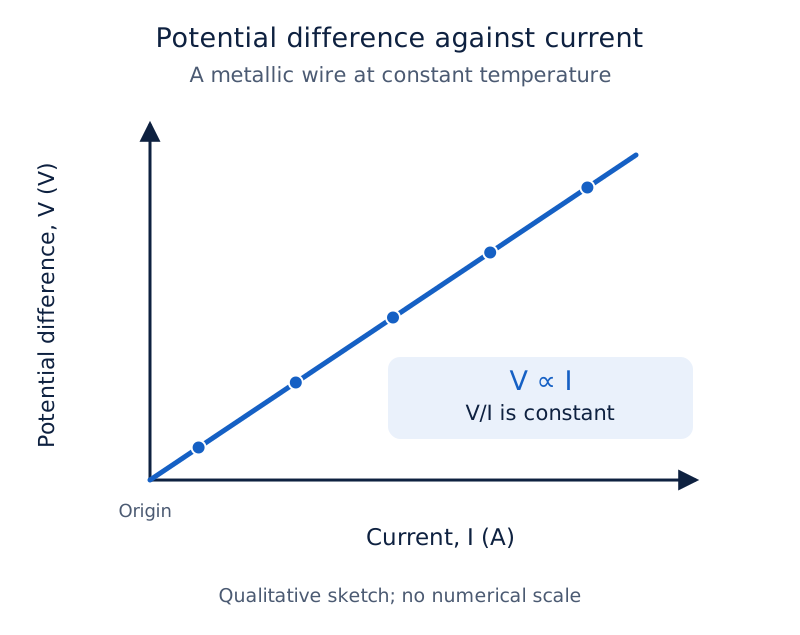
Current in amperes is on the horizontal axis and potential difference in volts on the vertical axis. The plotted points lie along a rising straight line through the origin.
Drawn by One Young India.
How do voltage and resistance determine current?
Worked example 4. A bulb filament has resistance 1200 Ω when connected to a 220 V source. Find the current.
Given: V = 220 V; R = 1200 Ω. Formula: I = V/R.
Substitute: I = 220/1200. Answer: approximately 0.18 A.
Worked example 5. An electric heater coil has resistance 100 Ω when connected to a 220 V source. Find its current.
Given: V = 220 V; R = 100 Ω. Formula: I = V/R.
Substitute: I = 220/100. Answer: 2.2 A.
The source potential difference is the same in these two examples. The heater coil’s lower resistance allows a larger current. Compare the complete voltage and resistance data before deciding which component carries more current.
Worked example 6. A heater draws 4 A at 60 V. What current will it draw at 120 V if its resistance remains unchanged?
Given: initial potential difference 60 V; initial current 4 A; new potential difference 120 V.
Formula: R = V/I; I = V/R.
Substitute: R = 60/4 = 15 Ω; new current I = 120/15.
Answer: 8 A. The unchanged resistance is essential to this calculation.
Derivation: Equivalent resistance of three resistors in series
Let , and be three resistances in series. The same current passes through each. Their potential differences are , and , and is the total potential difference.
- The total potential difference is the sum of the individual potential differences: .
- Let be the equivalent resistance, which draws the same current at the same total potential difference. Applying Ohm’s law gives .
- Apply Ohm’s law to each resistor: , and .
- Substitute these expressions into the total potential difference: . For a non-zero current, divide each term by .
Result: . The equivalent resistance of resistors in series equals the sum of their individual resistances.
Derivation: Equivalent resistance of three resistors in parallel
Let , and be three resistances in parallel. Each has the same potential difference . The branch currents are , and , and is the total current.
- The total current equals the sum of the branch currents: .
- Let be the equivalent resistance of the parallel combination. Applying Ohm’s law to the combination gives .
- Apply Ohm’s law to each branch: , and .
- Substitute into the total current: . For a non-zero potential difference, divide each term by .
Result: . The reciprocal of the equivalent resistance equals the sum of the reciprocals of the individual resistances.
What is induced magnetism, and why does induction precede attraction?
A magnet has north and south poles, the regions associated with its strongest magnetic effects. The north-seeking pole points approximately north when the magnet is free to turn; the south-seeking pole points approximately south. Like poles repel and unlike poles attract.
A magnetic material, such as iron, can acquire magnetism in the presence of a magnet. Induced magnetism is magnetism produced in a material by the influence of an external magnet. The material need not already be a permanent magnet.
What happens to an iron nail near a bar magnet?
- Bring the north pole of a bar magnet near an initially unmagnetised iron nail.
- The magnet induces magnetism in the nail before the nail is attracted towards it.
- The nearer end of the nail develops a south pole and the farther end develops a north pole.
- The attraction involving the nearer unlike pole is stronger than the repulsion involving the farther like pole, giving a net attraction.
This explains the statement induction precedes attraction. It describes the order of events: magnetism is induced first, and the resulting interaction draws the iron towards the magnet. Attraction does not prove that the iron was already a magnet.
Why is repulsion a stronger test of magnetism?
A magnet can attract an unmagnetised magnetic material by induction. It can also attract the unlike pole of another magnet. Attraction alone therefore does not distinguish between those possibilities. Repulsion between the appropriate ends establishes that both objects are magnetised.
If the inducing pole is reversed, the induced poles reverse too. The nearer end still becomes unlike the nearby inducing pole. Keep the position of the nail’s nearer end clear when assigning poles; merely saying that the nail becomes magnetic leaves the explanation incomplete.
Induced magnetism concerns a material acquiring magnetic properties under a magnet’s influence. It should not be confused with a cell driving electric charge around a conducting circuit. In the nail example, the bar magnet supplies the magnetising influence.
How do magnetic field lines describe a bar magnet?
A magnetic field is the region around a magnet where its magnetic influence can be detected. A magnetic compass contains a small magnetised needle that can turn. The needle responds to the magnetic field at its position.
Magnetic field lines represent the direction and relative strength of the field. The direction at a point is indicated by the north pole of a compass needle placed there. The field has both direction and magnitude, meaning its strength.
What properties must a field-line drawing show?
- Outside a bar magnet, field lines run from the north pole to the south pole.
- Inside the magnet, the direction is from south to north, completing closed curves.
- More closely spaced lines indicate a stronger field; they are crowded near the poles.
- No two field lines cross, because a compass needle cannot point in two field directions at the same point.
Photograph: Iron filings near the bar magnet align themselves along the field lines. The photograph shows a bar magnet labelled N at the left and S at the right. Iron filings form curved patterns around it and are crowded near its ends. N means north pole and S means south pole.
To obtain a filings pattern, place a bar magnet on paper fixed to a board, sprinkle iron filings around it and tap gently. The filings align in the magnet’s field. Their pattern reveals the field’s arrangement rather than a set of physical lines in space.
How can a compass trace a field line?
- Place a bar magnet on paper and mark its boundary.
- Put a small compass near the magnet’s north pole and mark the positions of both needle ends.
- Move the compass so its south end occupies the position previously occupied by its north end.
- Continue marking and moving the compass until the traced path approaches the magnet’s south pole.
- Join the marked points with a smooth curve and repeat from other starting positions.
What the figure shows
Compass tracing and field pattern
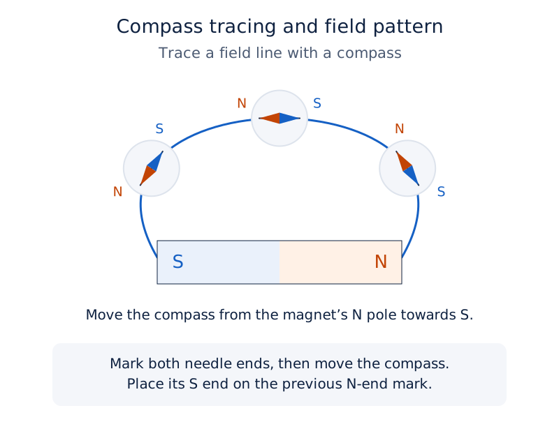
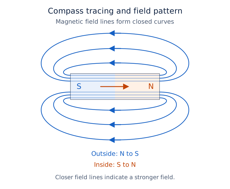
Figure 12.3 shows successive compass positions curving above a bar magnet with S on the left and N on the right. Figure 12.4 shows curved field lines with arrows directed from N towards S outside the magnet.
Drawn by One Young India.
Iron filings show a pattern; a compass also establishes direction. Use arrowheads to record that direction in a drawing. The bar magnet’s field is non-uniform, meaning that its strength or direction changes from place to place.
How do Earth’s magnetic field and neutral points affect a compass?
Earth’s magnetic field makes a freely suspended magnet or compass needle settle approximately along north and south. This directional behaviour provides evidence that Earth itself has a magnetic field. A nearby bar magnet can change the direction in which the compass settles.
The magnetic north-south direction is the direction indicated by a freely turning compass away from disturbing magnets. For field plotting over a small horizontal region, Earth’s horizontal magnetic field is treated as uniform. Uniform means the same strength and direction throughout that region.
How do uniform and non-uniform fields compare?
| Feature | Uniform field | Non-uniform field |
|---|---|---|
| Strength and direction | Remain the same across the region | Strength or direction varies with position |
| Field-line representation | Parallel, equally spaced lines with common arrow direction | Spacing or direction changes across the pattern |
| Relevant example | Earth’s horizontal field over a small plotting area | The field around a bar magnet |
A compass near a bar magnet responds to the resultant field, meaning the combined field at its position. Both Earth and the bar magnet contribute. A strong field from the bar magnet can therefore turn the compass away from its usual north-south direction.
What makes a point neutral?
A neutral point in a horizontal field plot is a position where the bar magnet’s field cancels Earth’s horizontal field. The two fields must be equal in magnitude and opposite in direction. Merely being weak or opposite is insufficient for complete cancellation.
At this point there is no resultant horizontal field to give a compass a definite horizontal direction. The individual contributions have not vanished: their combined horizontal effect is zero. A region with a very weak resultant field is not necessarily an exact neutral point.
How can the combined field be investigated?
- First use a small compass to plot Earth’s field without a bar magnet nearby.
- On another sheet, place a bar magnet along the magnetic north-south direction.
- Move the compass around the magnet and plot the combined field.
- Identify regions where the combined field is strong, very weak but non-zero, or neutral.
With the bar magnet’s north pole pointing magnetic north, the neutral points lie on the line through its centre perpendicular to its length. With its north pole pointing magnetic south, they lie on the extended line along its length, beyond the ends.
Note: These neutral-point positions refer to a horizontal plotting arrangement with Earth’s horizontal field. State the magnet’s orientation before identifying the positions; reversing the magnet changes where cancellation occurs.
Glossary
- Electric charge — A property of matter associated with electric forces, occurring as positive or negative charge.
- Free electrons — Electrons that are practically free to move within a material and can carry current.
- Quantisation of charge — The occurrence of a body’s charge in integral multiples of the elementary charge.
- Electric current — The rate at which electric charge passes through a cross-section of a conductor.
- Conventional current — Current direction defined as the direction in which positive electric charge would flow.
- Potential difference — The work done per unit charge moved between two points in a circuit.
- Resistance — The property of a conductor that opposes the flow of electric charge through it.
- Rheostat — A variable resistance used to regulate the current flowing through an electric circuit.
- Semiconductor — A material whose resistance to charge movement is intermediate between conductors and insulators.
- Accumulator — A rechargeable secondary cell that can be used again after it has been recharged.
- Induced magnetism — Magnetism acquired by a material under the influence of an external magnet.
- Magnetic field — The region around a magnet in which its magnetic influence can be detected.
- Uniform magnetic field — A magnetic field whose strength and direction remain the same throughout a region.
- Neutral point — A position where opposing magnetic field contributions cancel, giving zero resultant field in the specified arrangement.
Common errors and misconceptions
- Misconception: A neutral metal contains no charge. Correct: It contains positive and negative charges that balance overall, and some electrons can move through it.
- Misconception: Electron flow and conventional current have the same direction. Correct: Their directions are opposite in the external metallic circuit.
- Misconception: Opening the key removes the cell’s potential difference. Correct: It breaks the conducting path and stops current; a cell can maintain potential difference without supplying current.
- Misconception: An ammeter belongs across the component. Correct: An ammeter is connected in series; a voltmeter is connected across the two points being compared.
- Misconception: Ohm’s law applies without any temperature condition. Correct: For a given metallic wire, the proportional relationship requires its temperature to remain the same.
- Misconception: Attraction proves an iron object was already a magnet. Correct: An initially unmagnetised iron object can acquire induced magnetism and then be attracted.
- Misconception: Magnetic field lines can cross. Correct: Crossing would require two field directions at one point, which a compass needle cannot indicate.
- Misconception: Any weak-field region is a neutral point. Correct: A neutral point requires exact cancellation of the relevant equal and opposite field contributions.
Exam-style questions with model answers
Q1. Define electric current and state what a current of one ampere means. [2 marks]
- Electric current is the rate of flow of electric charge through a cross-section of a conductor.
- A current of one ampere means that one coulomb of charge passes through that cross-section in one second.
Q2. A bulb draws 0.5 A for 10 minutes. Using 1 minute = 60 seconds, calculate the charge passing through it, showing the time conversion and relationship used. [3 marks]
- The time must be expressed in seconds: 10 × 60 = 600 s. The given current is already in amperes, the appropriate unit for the calculation.
- Use Q = It, where Q is the charge passing through the bulb, I is the current and t is the time taken.
- Substituting gives Q = 0.5 × 600 = 300 C. Thus 300 coulombs of charge pass through the bulb during the stated time.
Q3. Explain potential difference, state its unit, and calculate the work done when 2 C moves between points at a potential difference of 12 V. [3 marks]
- Potential difference is the work done per unit charge moved between two points. Its SI unit is the volt, equivalent to one joule per coulomb.
- Use W = VQ, where W is work done, V is potential difference and Q is the charge moved. Here V = 12 V and Q = 2 C.
- Therefore W = 12 × 2 = 24 J. The transfer of two coulombs between the specified points involves twenty-four joules of work.
Q4. A heater draws 4 A at 60 V. Its resistance remains unchanged when the potential difference becomes 120 V. Calculate its resistance and new current, and state why the unchanged-resistance condition matters. [4 marks]
- Let R be resistance, V potential difference and I current. From V = IR, the initial resistance is found using R = V/I.
- Substitution gives R = 60/4 = 15 Ω. This resistance is calculated from the original potential difference and current supplied in the question.
- At the new potential difference, I = V/R = 120/15 = 8 A. The heater therefore draws a current of eight amperes.
- The unchanged-resistance condition permits using the original 15 Ω in the second calculation. Without that condition, the first resistance would not establish the new current.
Q5. Describe five steps or observations for investigating Ohm’s law using a resistance wire, cells, a key, an ammeter and a voltmeter. Include the temperature condition and expected relationship. [5 marks]
- Connect the resistance wire, key, source and ammeter in series. This places the ammeter in the path carrying the current through the wire.
- Connect the voltmeter in parallel across the two ends of the resistance wire so that it measures the potential difference across that wire.
- Begin with one cell, close the key and record the ammeter and voltmeter readings. These give a corresponding current and potential-difference pair.
- Repeat with two, three and four cells while keeping the wire’s temperature unchanged. Calculate potential difference divided by current for each pair of readings.
- The ratios are approximately constant, and the potential-difference against current graph is a straight line through the origin. This supports Ohm’s law under the stated condition.
Q6. An initially unmagnetised iron nail is brought near the north pole of a bar magnet. Explain induced magnetism, identify the induced poles, and explain why the nail is attracted. [3 marks]
- Induced magnetism is magnetism produced in a material by an external magnet. The nail acquires magnetism under the bar magnet’s influence before it is attracted.
- The end of the nail nearer the north pole becomes a south pole. The farther end becomes a north pole, so the nearer poles are unlike.
- The attraction at the nearer unlike pole exceeds the repulsion at the farther like pole. The resulting force is towards the bar magnet, illustrating that induction precedes attraction.
Q7. Give the directions of magnetic field lines outside and inside a bar magnet, explain what their spacing shows, explain why they cannot cross, and describe compass tracing. [5 marks]
- Outside a bar magnet, field lines run from the north pole to the south pole. Arrowheads on a field-line diagram show this direction.
- Inside the magnet, the direction is from south to north. The internal and external parts therefore form closed curves rather than lines with isolated ends.
- Closer spacing indicates a stronger magnetic field. Lines are crowded near the poles, where the magnetic influence is stronger than in regions with widely spaced lines.
- Field lines cannot cross: crossing would imply two magnetic field directions at one point. A compass needle placed there cannot simultaneously indicate both directions.
- Mark both ends of a compass needle, then move its south end to the previous north-end mark. Repeat and join the marked points with a smooth curve.
Q8. A bar magnet is placed along magnetic north-south on a horizontal plotting board. Define a neutral point, state the cancellation conditions, and explain how reversing the magnet changes the positions of the neutral points. [4 marks]
- A neutral point is a position where the bar magnet’s field cancels Earth’s horizontal magnetic field, leaving zero resultant horizontal field in the plotting arrangement.
- The two field contributions must be equal in magnitude and opposite in direction. A very weak field alone does not establish that a point is neutral.
- With the magnet’s north pole pointing magnetic north, neutral points lie on the line through its centre perpendicular to its length.
- With the magnet’s north pole pointing magnetic south, neutral points lie along the extended line of its length, beyond the ends. Reversal changes the cancellation positions.
Key takeaways
- Electric current is charge flow per unit time; use amperes, coulombs and seconds consistently in numerical calculations.
- Conventional current and electron flow have opposite directions in an external metallic circuit connected to a cell.
- Potential difference measures work per unit charge, while resistance expresses opposition to the flow of electric charge.
- An ammeter is connected in series, and a voltmeter is connected across the two points whose potential difference is measured.
- Ohm’s law relates potential difference and current for a given metallic wire provided its temperature remains the same.
- A bar magnet induces magnetism in nearby iron before attraction occurs; attraction alone does not prove prior magnetisation.
- Magnetic field lines form closed curves, indicate stronger fields by closer spacing, and do not cross one another.
- Neutral points require equal and opposite field contributions; their positions depend on the bar magnet’s orientation in Earth’s field.
Test yourself
Why can a neutral metal still carry electric current?
Its positive and negative charges balance overall, but some electrons are practically free to move. Directed motion of these electrons carries current.
What does the relation q = ne express?
Charge q is an integral multiple of the elementary charge e; n is an integer. This is called quantisation of charge.
What happens when the key in a simple bulb circuit is opened?
The conducting path breaks, current stops and the bulb goes out. The cell can still maintain a potential difference between its terminals.
How does an accumulator differ from a cell that cannot be recharged?
An accumulator is a secondary cell that can be recharged after use and then used again as a source.
What happens to current if resistance doubles at unchanged potential difference?
The current is halved because current equals potential difference divided by resistance, with the potential difference held constant.
Why is attraction alone insufficient to identify a permanent magnet?
An initially unmagnetised iron object can be attracted after acquiring induced magnetism. Attraction therefore does not establish that it was already magnetised.
What evidence of Earth’s magnetic field does a compass provide?
A freely turning compass needle settles approximately along north and south away from disturbing magnets, showing a directional magnetic influence.
Do the individual fields disappear at a neutral point?
No. The relevant fields remain individually present but cancel because they are equal in magnitude and opposite in direction.
Write about it
Turn a question from this chapter into a paper.
The Writing Studio has a structure guide, a rubric and citation tools for 15 formats, from essays to research papers. Drafting is free with an account. Learnacy Essential adds feedback from an AI writing coach and submission to The OYI Review.
Publication depends on review and is not guaranteed.