
Magnetism and Matter | ISC Class 12 Physics Notes
On this page
This note covers magnetic dipoles and field lines, current loops and revolving electrons, bar magnets and solenoids, torque and magnetic energy, magnetisation, susceptibility, permeability, magnetic materials, temperature effects, hysteresis, electromagnets and permanent magnets.
What are magnetic poles and magnetic field lines?
A bar magnet has two poles. When freely suspended, its north pole points approximately towards geographic north and its south pole approximately towards geographic south. Like poles repel, while unlike poles attract. These interactions help identify the magnetic character of a body.
A magnetic dipole is the elementary magnetic arrangement represented by a small bar magnet or a current loop. Cutting a bar magnet across or along its length produces smaller magnets, each with a north and a south pole. It does not separate the poles.
How is the field represented?
The magnetic field B is a vector quantity, meaning that it has magnitude and direction. Its SI unit is tesla, symbol T. SI means International System of Units. Magnetic field lines give a visual representation of this field.
The field is defined through its magnetic force on moving charge: F = |q|vB sinα. Here F is the force magnitude, |q| the charge magnitude, v its speed and α the angle between velocity and field. The force is perpendicular to velocity and field, with its sense depending on the charge sign.
- Magnetic field lines form continuous closed loops, continuing through the magnet as well as outside it.
- The tangent to a line at a point gives the direction of the net magnetic field there.
- More closely spaced lines indicate a stronger field; lines spread farther apart indicate a weaker field.
- Two field lines do not intersect, since an intersection would assign two different directions to the field at one point.
Outside a bar magnet, field lines run from its north pole to its south pole. Inside, they return from south to north. A small compass placed at successive positions reveals the local field direction through the orientation of its needle.
What the figure shows
Bar magnet and solenoid field patterns
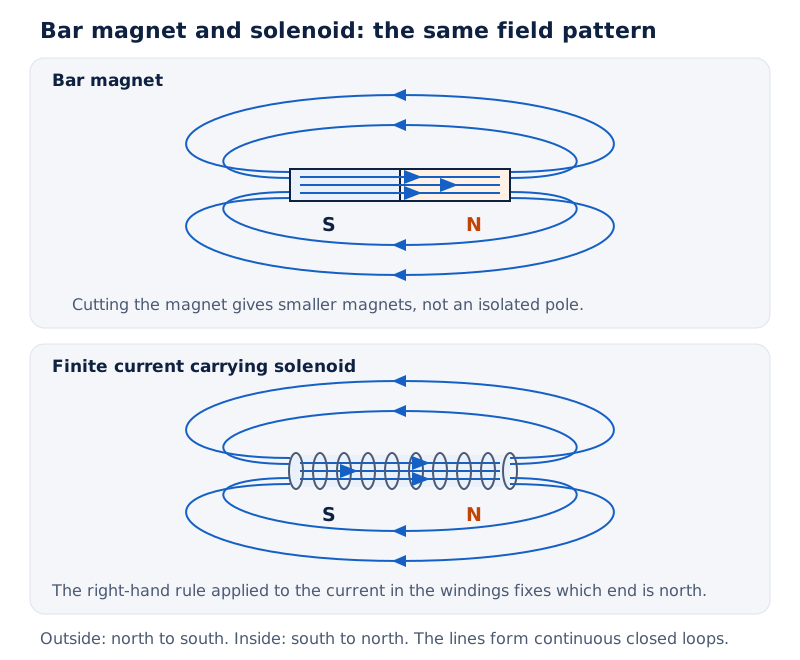
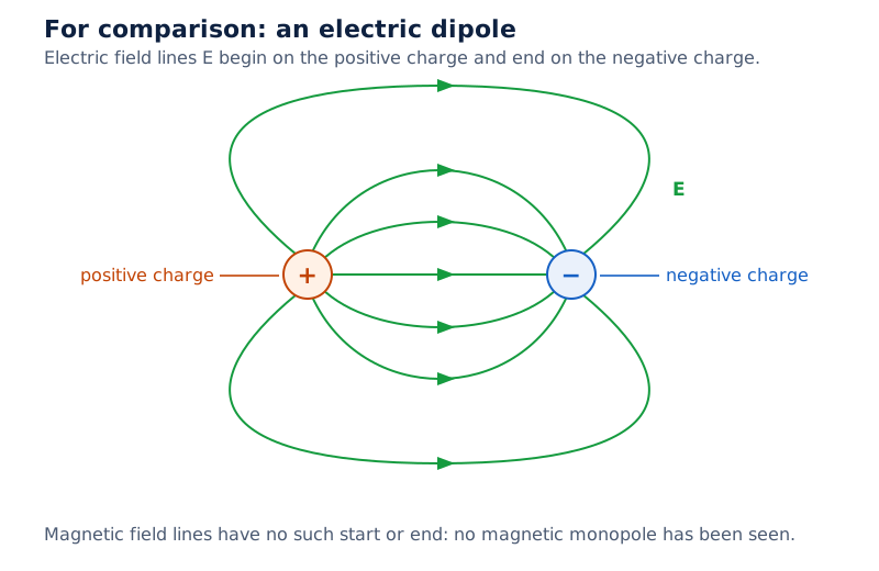
The drawing places a bar magnet beside a finite current-carrying solenoid. Both show lines continuing through their interiors and curving around outside. A third drawing shows an electric dipole, with positive and negative charges.
Drawn by One Young India.
Note: Magnetic field lines do not give the force direction on a moving charge. The magnetic force is perpendicular to both the velocity and the field when it is non-zero.
How does a current loop behave as a magnetic dipole?
A current loop is a closed conducting path carrying electric current. Its field resembles that of a magnetic dipole at distances large compared with the loop's size. It also experiences a turning effect in an external field, like a magnetic needle.
The magnetic dipole moment m measures the magnetic strength and orientation of a loop. Let I be the current, measured in amperes, symbol A, and let A denote the area enclosed by one turn, measured in square metres, m². Context distinguishes area A from the ampere unit.
m = IA
For a coil with N identical turns, N is the number of turns and the moments add. The area vector is perpendicular to the plane of the coil. The moment has this same direction, chosen using the current.
m = NIA
The SI unit of magnetic dipole moment is A m². It can also be written J T⁻¹, where J is the joule, the unit of energy. A moment is a vector even when an equation gives only its magnitude.
How does the right-hand rule fix the direction?
Curl the fingers of the right hand in the direction of conventional current, the direction positive charge would move. The extended thumb points along the magnetic moment. Viewed from a face, anticlockwise current makes that face north-like; clockwise current makes it south-like.
Worked example 1. A closely wound solenoid has 800 turns, cross-sectional area 2.5 × 10⁻⁴ m² and current 3.0 A. Find its magnetic moment.
Formula: m = NIA. Substitute: m = 800 × 3.0 × 2.5 × 10⁻⁴.
Answer: m = 0.60 A m². Its direction is along the solenoid axis, fixed by the right-hand rule. The opposite ends behave as the poles of a bar magnet.
A solenoid is a coil wound in many closely spaced turns. Its resemblance to a magnet concerns both its external field pattern and its response to an applied field. It does not require separate magnetic charges at its ends.
Why does a revolving electron have a magnetic moment?
An electron has negative electric charge. Its orbital motion can therefore be treated as an equivalent current loop. This gives an orbital magnetic moment, the magnetic moment associated with revolution around the nucleus in the circular-orbit model.
Let e be the positive magnitude of the electron's charge, r the orbit radius, v the electron's speed and t the time for one revolution. Let mₑ denote the electron mass. The symbol π is the ratio of a circle's circumference to its diameter.
How are current and orbital moment related?
The electron travels a circumference 2πr in one revolution, so t = 2πr/v. The magnitude of the equivalent current is charge passing per revolution divided by the revolution time. Conventional current runs opposite to the electron's motion because the electron is negatively charged.
I = e/t
The circular orbit encloses area A = πr². Multiplying this area by the equivalent current gives the magnitude of the orbital magnetic moment:
m = evr/2
Angular momentum L is the rotational momentum of the orbiting electron; for this circular orbit its magnitude is L = mₑvr. Consequently, the magnitudes satisfy m/L = e/(2mₑ). The magnetic moment and angular momentum point in opposite directions.
What does the circular-orbit description explain?
In the Bohr model of hydrogen, the atom is represented by an electron revolving around its nucleus in an allowed orbit. The current-loop calculation explains the orbital contribution to the electron's magnetic moment within that model.
Circulating currents provide a useful link between electricity and magnetism. They do not explain every magnetic moment: an electron also possesses an intrinsic magnetic moment, meaning one that is not accounted for by orbital circulation. Orbital motion and intrinsic magnetic moment must therefore be distinguished.
How are a bar magnet and a solenoid equivalent?
A finite solenoid is a solenoid of limited length. Its magnetic field pattern resembles that of a bar magnet. Lines emerge from one end, enter the other and continue through the interior. A compass moved around either arrangement gives similar deflections.
The magnetic moment of a bar magnet equals that of an equivalent solenoid producing the same magnetic field. The direction of the bar magnet's moment is from its south pole towards its north pole. Cutting either arrangement produces smaller dipole arrangements rather than an isolated pole.
What are axial and equatorial positions?
The axial line, also called the end-on line, extends along the magnet's length through its centre and poles. The equatorial line, or broadside-on line, passes through its centre perpendicular to this axis.
| Position | Field direction for a short dipole | Comparison at equal large distance |
|---|---|---|
| Axial | Parallel to the magnetic moment | Twice the equatorial field magnitude |
| Equatorial | Opposite to the magnetic moment | Half the axial field magnitude |
These comparisons apply at distances much greater than the magnet's size. In this far-field approximation, both field magnitudes decrease with the cube of distance from the centre. The magnet's finite size matters when the observation point is nearby.
Why does the field form closed loops?
An isolated magnetic pole would be a magnetic monopole. No magnetic monopoles have been seen so far. The closed-loop description contrasts with electric field lines, which can begin on positive charges and end on negative charges.
Magnetic flux, denoted by φ, measures the magnetic field passing through an oriented surface. For a uniform field and a plane surface, φ = BA cosβ, where A is the surface area and β the angle between the field and the surface normal. The SI unit of magnetic flux is weber, Wb.
Gauss's law for magnetism states that the net magnetic flux through a closed surface is zero. Field lines entering the surface are balanced by lines leaving it; zero net flux does not mean zero field everywhere.
What torque acts on a dipole in a uniform magnetic field?
A uniform magnetic field has the same magnitude and direction throughout the region considered. A magnetic dipole in such a field has zero net force but can experience torque τ, a turning effect. The SI unit of torque is newton metre, N m.
Let θ be the angle between the magnetic moment and the external magnetic field. The torque magnitude is:
τ = mB sinθ
The vector relation is τ = m × B, where × between vectors denotes the vector or cross product. Its direction is perpendicular to the two vectors, as fixed by the right-hand rule. The torque tends to align the moment with the field.
Derivation: Torque on a rectangular current loop
Take a rectangular loop with side lengths a and b and area A = ab. Its normal makes angle θ with the uniform field. Choose the opposite sides of length b perpendicular to the field; let F denote each force's magnitude.
- Each of these opposite sides experiences a force of magnitude F = IbB. The forces are equal and opposite, so their resultant force is zero.
- The forces act along different lines. They form a couple, meaning an equal and opposite force pair with a turning effect. Their perpendicular separation is a sinθ.
- The couple's torque is force multiplied by separation: τ = IbB × a sinθ = IAB sinθ. The other opposite sides contribute no resultant torque.
- For N identical turns, the torque becomes NIAB sinθ. Substituting m = NIA gives the dipole form.
τ = NIAB sinθ
Which orientations have zero torque?
The torque is zero for θ = 0° and θ = 180°, and greatest at θ = 90°. Zero torque is therefore insufficient to decide stability: the parallel and antiparallel arrangements must be distinguished by their response to a small displacement.
Worked example 2. A short bar magnet at 30° to a uniform field of 0.25 T experiences torque 4.5 × 10⁻² N m. Find its magnetic moment. Use sin30° = 0.5.
Formula: m = τ/(B sinθ). Substitute: m = 0.045/(0.25 × 0.5).
Answer: m = 0.36 A m². The angle belongs between the moment and the field, not between the field and a coil's plane.
How are magnetic energy, equilibrium and work connected?
Magnetic potential energy U is the energy associated with a dipole's orientation in an external field. Choose zero energy when its moment is perpendicular to the field. For a fixed dipole moment in a uniform field:
U = −mB cosθ
The SI unit of potential energy is joule, J. In stable equilibrium, a small angular displacement produces a torque towards the original orientation. This occurs with the moment parallel to the field, θ = 0°, where the energy is minimum, −mB.
In unstable equilibrium, a small angular displacement produces a torque away from the original orientation. The antiparallel arrangement, θ = 180°, has maximum energy, +mB. Both equilibrium orientations have zero torque, despite their different stability.
How is work calculated?
For slow rotation by an external agent, with no change in kinetic energy, the external work W equals the potential-energy change. Write U(initial) and U(final) for the energies in the initial and final orientations respectively; θᵢ and θᶠ are the corresponding angles.
W = U(final) − U(initial)
Equivalently, W = mB(cosθᵢ − cosθᶠ). Positive external work increases the dipole's potential energy. The angle dependence must be included: the final torque alone does not determine the work done throughout a rotation.
Worked example 3. A magnet of moment 0.32 J T⁻¹ is placed in a uniform field of 0.15 T. Find its energies in stable and unstable equilibrium.
Formula: U = −mB cosθ. Substitute: mB = 0.32 × 0.15 = 0.048 J.
Answer: Stable equilibrium has U = −0.048 J at 0°; unstable equilibrium has U = +0.048 J at 180°. The perpendicular orientation is the chosen zero of energy.
Worked example 4. A magnet of moment 1.5 J T⁻¹ initially points along a uniform field of 0.22 T. Find the external work for slow rotation to 90° and to 180°, each starting from that initial position.
Formula: U = −mB cosθ; W = U(final) − U(initial). Substitute: U(initial) = −1.5 × 0.22 = −0.33 J; the final energies are 0 J and +0.33 J.
Answer: W = 0.33 J for 90° and 0.66 J for 180°. The corresponding final torques are 0.33 N m and zero.
How are magnetisation, susceptibility and permeability related?
Magnetisation M is the net magnetic dipole moment per unit volume of a material. Let mₙₑₜ denote its net moment and V its volume. Atomic moments add as vectors, so a material can contain magnetic atoms while having zero bulk magnetisation.
M = mₙₑₜ/V
The SI unit of magnetisation is A m⁻¹. Magnetic intensity H represents the magnetising field associated with external currents. It is distinguished from B, the total magnetic field in the material. The SI unit of magnetic intensity is also A m⁻¹.
Let μ₀ be the permeability of free space. Permeability describes the relation between magnetic field and magnetic intensity. The defining relation for H can be rearranged to give:
B = μ₀(H + M)
Magnetic susceptibility χ measures the magnetisation produced per unit magnetic intensity. For a linear material, where magnetisation is proportional to the applied intensity, M = χH. Susceptibility is dimensionless, meaning that it has no physical unit.
Derivation: Susceptibility and relative permeability
Let μ denote the material's magnetic permeability, and μᵣ = μ/μ₀ its dimensionless relative permeability. Use the linear relation at the stated conditions.
- Begin with B = μ₀(H + M), which combines the external and material contributions.
- Replace M by χH to obtain B = μ₀(1 + χ)H.
- Compare with B = μH = μ₀μᵣH and identify the factor multiplying H.
μᵣ = 1 + χ
The SI unit of magnetic permeability is T m A⁻¹. Negative susceptibility gives a relative permeability below one; small positive susceptibility gives a value slightly above one. Ferromagnetic behaviour is generally not described by one constant susceptibility throughout a complete magnetisation cycle.
How does a solenoid magnetise its core?
For a long solenoid, let n be the number of turns per unit length. Then H = nI. Its field without a magnetic core is B₀ = μ₀nI, where B₀ denotes that original field. A core adds the contribution associated with M.
Worked example 5. A long solenoid has 1000 turns per metre, current 2 A and a core of relative permeability 400. Find H, M and B. Use μ₀ = 4π × 10⁻⁷ T m A⁻¹.
Formula: H = nI; M = (μᵣ − 1)H; B = μ₀μᵣH. Substitute: H = 1000 × 2; M = 399 × 2000; B = 4π × 10⁻⁷ × 400 × 2000.
Answer: H = 2000 A m⁻¹; M ≈ 8 × 10⁵ A m⁻¹; B ≈ 1.0 T. The core's contribution accounts for the large increase in field.
How do diamagnetic and paramagnetic substances differ?
Diamagnetic substances acquire weak magnetisation opposite to the applied magnetic intensity. Their atoms have zero resultant magnetic moment before the field is applied. The field changes the orbital motion of electrons and induces a resultant moment opposing the applied field.
They tend to move from the stronger to the weaker part of a non-uniform field. Their susceptibility is negative, and their relative permeability is below one. Examples include bismuth, copper, lead, silicon, water and sodium chloride.
The field inside a diamagnetic material is reduced. In most cases, this reduction is slight, being one part in 10⁵. Diamagnetism is present in all substances, but its effect is so weak in most cases that other magnetic effects obscure it.
Why do paramagnetic materials respond differently?
Paramagnetic substances have atoms, ions or molecules with permanent magnetic dipole moments. Random thermal motion prevents a net magnetisation without an external field. An applied field favours alignment, giving weak magnetisation in the same direction as the field.
Paramagnetic materials tend to move from weaker to stronger regions of a non-uniform field. Their susceptibility is small and positive, and their relative permeability is slightly above one. Examples include aluminium, sodium, calcium and copper chloride.
Oxygen at standard temperature and pressure is paramagnetic, while nitrogen under those conditions is diamagnetic. The abbreviation STP means standard temperature and pressure. In most cases, the field enhancement in a paramagnetic sample is slight, being one part in 10⁵.
What the figure shows
Field lines near magnetic materials
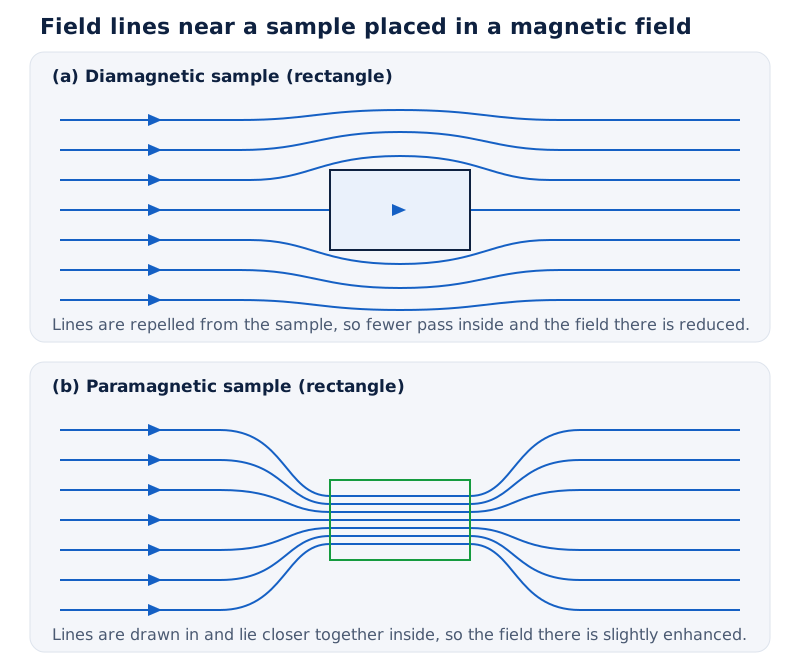
Drawing (a) shows field lines bending away from a rectangular diamagnetic sample, leaving fewer lines inside. Drawing (b) shows lines becoming more closely spaced inside a paramagnetic sample.
Drawn by One Young India.
| Property | Diamagnetic | Paramagnetic |
|---|---|---|
| Induced bulk magnetisation | Opposite to applied intensity | Along applied intensity |
| Susceptibility | Negative | Small and positive |
| Non-uniform field response | Weak repulsion towards weaker field | Weak attraction towards stronger field |
| Freely suspended small bar | Sets perpendicular to the horizontal field | Sets parallel to the horizontal field |
| Example | Bismuth | Aluminium |
What causes ferromagnetism and how does temperature affect it?
Ferromagnetic substances become strongly magnetised in an external field. They are strongly attracted towards the stronger region of a non-uniform field. Examples include iron, cobalt and nickel. Their susceptibility is large and positive, and their relative permeability is much greater than one.
A domain is a region in which atomic magnetic moments spontaneously align in a common direction. An unmagnetised specimen contains domains with different orientations, so their contributions can cancel at the scale of the whole specimen.
How does an applied field change domains?
In an applied field, domains orient towards the field and favourably oriented domains grow. This produces a large net magnetisation and concentrates field lines inside the material. A freely suspended small ferromagnetic bar sets parallel to a horizontal magnetic field.
What the figure shows
Magnetic domains
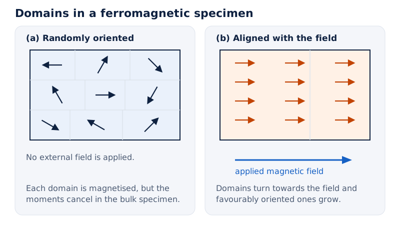
Drawing (a) shows many small regions with arrows pointing in different directions. Drawing (b) shows arrows aligned to the right, with an external-field arrow below the sample pointing in that same direction.
Drawn by One Young India.
After the external field is removed, magnetisation persists in some ferromagnetic materials. These are hard magnetic materials. In soft ferromagnetic materials such as soft iron, magnetisation disappears on removing the external field. The distinction determines their uses.
What are Curie's law and Curie temperature?
For paramagnetic materials, Curie's law gives χ = C/T, where C is the material's Curie constant and T here denotes absolute temperature in kelvin, symbol K. In this equation T means temperature, not the tesla unit used after a field value.
This relation applies in the paramagnetic regime before saturation, where complete alignment limits further magnetisation. At constant magnetic intensity, raising temperature reduces magnetisation. Diamagnetic susceptibility is independent of temperature in this description; ferromagnetic susceptibility has a more complicated temperature dependence.
The Curie temperature is the temperature at which a ferromagnetic material becomes paramagnetic on heating. Thermal disturbance breaks down the domain ordering. The disappearance of magnetisation with temperature is gradual, so it should not be described as remaining unchanged until an abrupt loss.
What does a magnetic hysteresis loop show?
Magnetic hysteresis is the lag of magnetic response behind changes in the magnetising intensity. A graph of B against H records how a ferromagnetic sample responds during a complete magnetising cycle. Its behaviour depends on previous magnetisation as well as the present applied intensity.
How is the cycle traced?
- Starting with an unmagnetised sample, increase positive H. The field B rises towards saturation, where further increases produce comparatively little additional magnetisation.
- Reduce H to zero. The sample retains a residual magnetic flux density, rather than returning along its original magnetising curve.
- Apply H in the reverse direction. A finite reverse intensity is needed to bring B to zero.
- Continue towards reverse saturation, then reverse the changes again. The return path completes a closed loop.
Retentivity is the residual magnetic flux density at zero magnetising intensity after the material has been magnetised to saturation. It describes how well the material retains magnetism. On the B-H loop, it is read at the intercept on the B axis.
Coercive force, also called coercivity in this setting, is the magnitude of reverse magnetic intensity needed to reduce B to zero after saturation. Despite its name, it is a magnetic intensity, measured in A m⁻¹, not a mechanical force measured in newtons.
Why does the area enclosed matter?
The area enclosed by the B-H loop represents energy dissipated per unit volume in one complete magnetisation cycle. A narrow loop indicates small hysteresis loss. This matters in a transformer core, whose magnetisation is repeatedly reversed by alternating current.
Diagram
Magnetic hysteresis loop
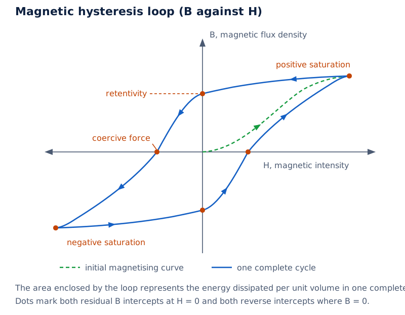
Draw H horizontally and B vertically. Mark positive and negative saturation, the residual B intercepts at H = 0, and the reverse-H intercepts where B = 0. Add arrows following a complete cycle and label retentivity and coercive force.
Drawn by One Young India.
A single ratio B/H cannot capture the whole loop. At the same applied intensity, different magnetic states are possible depending on the previous cycle. Material selection must therefore consider retention, ease of reversal and energy loss, rather than permeability alone.
How are electromagnets and permanent magnets selected?
An electromagnet is a magnet produced by electric current, commonly using a coil around a soft magnetic core. The current magnetises the core and enhances the field. Its magnetic action can be controlled by changing the current or switching it off.
What controls an electromagnet's strength?
For a long solenoid, the magnetising intensity is H = nI. Increasing current while keeping the turns per unit length constant increases H. Increasing turns per unit length at constant current also increases H. The core's magnetic response determines the resulting total field.
A high-permeability core produces a large field for a given magnetising intensity. However, near saturation, further increases in magnetising intensity produce relatively little extra magnetisation. An unlimited proportional increase in strength should not be assumed for a ferromagnetic core.
| Use | Desired behaviour | Material choice or property |
|---|---|---|
| Temporary electromagnet | Easy magnetisation and little residual magnetism after switching off | Soft magnetic material with low coercive force |
| Permanent magnet | Retains magnetisation and resists demagnetisation | Hard magnetic material with high retentivity and high coercive force |
| Transformer core | Easy repeated reversal with small energy loss | Soft magnetic material with high permeability and a narrow hysteresis loop |
A permanent magnet retains its magnetic properties for a long time at room temperature. Alnico is a hard magnetic alloy containing iron, aluminium, nickel, cobalt and copper. Lodestone is another material in which magnetisation persists. Such materials can be used as compass needles.
How do the dipole equations apply to a coil?
Worked example 6. A solenoid has 2000 turns, cross-sectional area 1.6 × 10⁻⁴ m² and current 4.0 A. Its axis is at 30° to a uniform external field of 7.5 × 10⁻² T. Find its moment, net force and torque. Use sin30° = 0.5.
Formula: m = NIA; τ = mB sinθ. Substitute: m = 2000 × 4.0 × 1.6 × 10⁻⁴ = 1.28 A m²; τ = 1.28 × 0.075 × 0.5.
Answer: The moment is 1.28 A m², net force is 0 N, and torque is 0.048 N m. A uniform field can rotate a dipole without producing a resultant translational force.
Glossary
- Magnetic dipole — An elementary magnetic arrangement represented by a small bar magnet or a current loop.
- Magnetic moment — A vector specifying a dipole's magnetic strength and orientation, measured in ampere square metres.
- Solenoid — A coil of closely spaced turns that produces a magnetic field when carrying current.
- Magnetisation — The net magnetic dipole moment per unit volume of a sample.
- Magnetic intensity — The magnetising field associated with external currents, distinguished from the total magnetic field in matter.
- Susceptibility — The dimensionless ratio of magnetisation to magnetic intensity in the linear response description.
- Relative permeability — The dimensionless ratio of a material's magnetic permeability to that of free space.
- Diamagnetism — A magnetic response in which induced magnetisation opposes the applied magnetic intensity.
- Paramagnetism — Weak magnetisation along an applied field arising from the response of permanent atomic magnetic moments.
- Domain — A region of a ferromagnetic material with magnetic moments aligned in a common direction.
- Curie temperature — The temperature at which a ferromagnetic material becomes paramagnetic on heating.
- Hysteresis — Dependence of magnetic response on previous magnetisation, producing different paths during a magnetising cycle.
- Retentivity — Residual magnetic flux density at zero magnetising intensity after magnetisation to saturation.
- Coercive force — The reverse magnetic intensity needed to reduce magnetic flux density to zero after saturation.
Common errors and misconceptions
- Misconception: Cutting a bar magnet isolates its poles. Correct: Each piece is another magnet with both poles, whether the original is cut along or across its length.
- Misconception: Magnetic field lines end at the south pole. Correct: They continue through the magnet from south to north, completing closed loops with the external lines.
- Misconception: The angle in τ = mB sinθ is measured from the coil's plane. Correct: It is measured between the moment, normal to the plane, and the field.
- Misconception: Zero torque means stable equilibrium. Correct: Parallel alignment is stable, while antiparallel alignment is unstable; both have zero torque before a displacement.
- Misconception: Magnetisation, magnetic intensity and magnetic field are interchangeable. Correct: They represent different quantities; M and H use A m⁻¹, whereas B uses tesla.
- Misconception: Every ferromagnet remains permanently magnetised. Correct: Magnetisation persists in some hard magnetic materials, while soft magnetic materials readily lose it after removal of the applied field.
- Misconception: High coercive force is desirable for every magnetic core. Correct: Permanent magnets need resistance to demagnetisation, while transformer cores need easy reversal and a narrow loop.
Exam-style questions with model answers
Q1. State two properties of magnetic field lines and explain why they cannot intersect. [2 marks]
- Magnetic field lines form continuous closed loops, passing through the magnet as well as the surrounding space.
- They cannot intersect because the tangent specifies the unique net field direction at a point; an intersection would imply two directions.
Q2. A solenoid has 800 turns, area 2.5 × 10⁻⁴ m² per turn and current 3.0 A. Calculate its magnetic moment and state its direction. [3 marks]
- The magnetic moment magnitude is m = NIA, where N is the number of turns, I the current and A the area enclosed by each turn. Each turn contributes to the total moment.
- Substitution gives m = 800 × 3.0 × 2.5 × 10⁻⁴ = 0.60 A m².
- The moment points along the solenoid axis, with direction fixed by curling the right-hand fingers along the current and extending the thumb.
Q3. A short magnet has moment 0.32 J T⁻¹ and lies in a uniform field of 0.15 T. Taking potential energy as zero at perpendicular alignment, find its stable and unstable orientations and the energy at each. [4 marks]
- The stable orientation is parallel to the field, at an angle of 0°. A small angular displacement produces a restoring torque.
- Using U = −mB cosθ, its energy is −0.32 × 0.15 = −0.048 J.
- The unstable orientation is antiparallel, at 180°. A small angular displacement produces a torque that increases the departure from this orientation.
- The energy there is +mB = +0.048 J, the maximum for the specified field and moment.
Q4. Compare diamagnetic, paramagnetic and ferromagnetic materials in terms of magnetisation, susceptibility, non-uniform-field response, microscopic origin and examples. [5 marks]
- Diamagnetic magnetisation opposes the applied field. Paramagnetic magnetisation is weak and parallel to it, whereas ferromagnetic magnetisation is strong and parallel to it.
- Susceptibility is negative for diamagnetic materials, small and positive for paramagnetic materials, and large and positive for ferromagnetic materials.
- In a non-uniform field, diamagnetic samples move towards weaker regions. Paramagnetic samples are weakly attracted towards stronger regions, while ferromagnetic samples are strongly attracted.
- Diamagnetism involves induced moments in atoms with no resultant moment initially. Paramagnetic atoms possess permanent moments; ferromagnetic materials contain domains with aligned moments.
- Bismuth is a diamagnetic example, aluminium is paramagnetic, and iron is ferromagnetic. These examples represent different magnetic responses rather than identical strengths of attraction.
Q5. Explain a B-H hysteresis loop, defining retentivity and coercive force, and use it to justify material choices for a permanent magnet and a transformer core. [5 marks]
- The B-H loop traces magnetic flux density B against magnetic intensity H during a complete magnetising cycle. Its separate forward and return paths show dependence on previous magnetisation.
- Retentivity is the residual B at H = 0 after saturation. A high value helps a permanent magnet retain its magnetic state after the applied field is removed.
- Coercive force is the reverse H needed to reduce B to zero. A permanent magnet needs high coercive force to resist demagnetisation.
- The enclosed loop area represents energy dissipated per unit volume in one complete cycle. A narrower loop therefore corresponds to smaller hysteresis loss.
- A transformer core should have high permeability and low coercive force with a narrow loop, so its magnetisation reverses readily with small energy loss.
Q6. A solenoid has 2000 turns of area 1.6 × 10⁻⁴ m² each and carries 4.0 A. Its axis is at 30° to a uniform external field of 7.5 × 10⁻² T. Calculate magnetic moment, net force and torque, and state the torque's tendency. Use sin30° = 0.5. [4 marks]
- The moment is m = NIA = 2000 × 4.0 × 1.6 × 10⁻⁴ = 1.28 A m², directed along the solenoid axis.
- The net force is zero because the external magnetic field is uniform across the dipole.
- The torque magnitude is τ = mB sinθ = 1.28 × 0.075 × 0.5 = 0.048 N m.
- The torque tends to rotate the magnetic moment towards alignment with the applied field, even though the resultant force is zero.
Q7. State Curie's law for paramagnetic susceptibility, defining its symbols, and explain the effect of increasing temperature while the law applies. [2 marks]
- Curie's law is χ = C/T, where χ is magnetic susceptibility, C the material's Curie constant and T absolute temperature in kelvin.
- Increasing temperature reduces susceptibility; at constant magnetic intensity, magnetisation decreases because thermal disturbance opposes alignment.
Key takeaways
- A current loop behaves as a magnetic dipole; its moment depends on current, enclosed area and number of turns.
- Magnetic field lines form closed loops, and their tangent gives the local direction of the net field.
- A dipole in a uniform field has zero net force but can experience torque tending to align its moment.
- Parallel alignment is stable and has minimum potential energy; antiparallel alignment is unstable and has maximum potential energy.
- Magnetisation is moment per volume, while susceptibility measures the material's response to magnetic intensity in the linear description.
- Diamagnetic materials oppose the applied field; paramagnetic and ferromagnetic materials develop magnetisation along it with different strengths.
- Ferromagnetic domains explain strong magnetisation; heating to the Curie temperature changes a ferromagnetic material into a paramagnetic material.
- Permanent magnets require retention and resistance to demagnetisation; transformer cores require easy reversal with small hysteresis loss.
Test yourself
What happens when a bar magnet is cut lengthwise?
Each piece remains a magnet with both a north pole and a south pole; isolated poles are not produced.
In which direction does the moment of a current loop point?
It points perpendicular to the loop, along the thumb when the right-hand fingers curl in the conventional-current direction.
Why is an electron's orbital moment opposite to its angular momentum?
The electron is negatively charged, so its equivalent conventional current circulates opposite to its direction of motion.
How does a short magnet's equatorial field compare with its axial field at the same large distance?
The equatorial field has half the axial magnitude and points opposite to the magnet's magnetic moment.
Can a dipole experience torque when its net force is zero?
Yes. In a uniform field the net force is zero, but a misaligned dipole can experience a turning couple.
What does negative magnetic susceptibility indicate?
It indicates a diamagnetic response, with induced magnetisation directed opposite to the applied magnetic intensity.
Why can an unmagnetised ferromagnet contain magnetised domains?
Different domains can have different orientations, so their magnetic moments cancel in the bulk specimen.
Why is a narrow hysteresis loop useful for a transformer core?
Its small enclosed area means a smaller energy loss per unit volume during each complete magnetisation cycle.
Write about it
Turn a question from this chapter into a paper.
The Writing Studio has a structure guide, a rubric and citation tools for 15 formats, from essays to research papers. Drafting is free with an account. Learnacy Essential adds feedback from an AI writing coach and submission to The OYI Review.
Learnacy Essential is ₹1,499 for the year. Publication depends on review and is not guaranteed.