
Current Electricity | CBSE Class 12 Physics Notes
On this page
Watch & explore
Start with a few high-quality watches, then dive into the notes below.

Learnacy Labs Try it hands-on: open the Electricity lab
This note covers electric current, Ohm’s law, resistance and resistivity, electron drift, mobility, temperature effects, electrical energy and power, cells and internal resistance, cell combinations, Kirchhoff’s rules, and the Wheatstone bridge.
What is electric current, and how is it maintained in a conductor?
How is the rate of charge flow measured?
Definition: Electric current is the net charge crossing a specified area per unit time. Its sign refers to a chosen direction across that area.
For a steady current, charge passes at a constant rate. For a current that changes with time, the rate must be evaluated over an increasingly small time interval:
Here or is charge in coulombs and or is time in seconds. The SI unit of current is the ampere, , with .
Conventional current follows the direction of positive charge flow. In a metal, mobile electrons drift in the opposite direction. Positive ions remain fixed in the solid background. In electrolytes, both positive and negative ions can carry current.
Why is random electron motion insufficient?
Electrons have thermal motion even without an applied electric field. Their velocities point randomly, so motion in one direction is balanced, on average, by motion in the opposite direction. The average velocity and net current are then zero.
An applied electric field gives electrons a small directed drift. Merely placing opposite charges at a conductor’s ends produces a temporary current: electron motion neutralises those charges. A cell maintains the electric field by supplying energy and sustaining charge separation.
Steady current requires a closed circuit and an agency that moves charge from lower to higher potential energy within the source. The conductor itself does not provide the energy needed to sustain the flow.
Note: Current is a scalar, despite the arrows used to indicate its direction in circuits. Current density is a vector; circuit currents combine algebraically at a junction.
How do Ohm’s law, resistance and resistivity describe a conductor?
What is the condition for Ohm’s law?
Ohm’s law states that current through an ohmic conductor is proportional to the potential difference across it, provided temperature and other relevant physical conditions remain constant and the applied field is within the ohmic range.
Here is potential difference in volts, is current in amperes, and is resistance. The SI unit of resistance is the ohm, , where .
The ratio of voltage to current can define a resistance at a particular operating point even for a non-ohmic device. The additional requirement of Ohm’s law is that this ratio stays constant as voltage changes under the stated conditions.
How does the conductor’s shape matter?
For a uniform conductor of a given material at a fixed temperature, resistance increases with length and decreases with cross-sectional area. A longer conducting path and a narrower cross-section each increase the resistance.
Here is length in metres, is cross-sectional area in square metres, and is resistivity. The SI unit of resistivity is the ohm metre, . Resistivity depends on material and physical conditions, rather than the conductor’s dimensions.
| Quantity | Meaning | Effect of geometry at fixed conditions |
|---|---|---|
| Resistance | Opposition associated with a particular conductor | Depends on length and cross-sectional area |
| Resistivity | Electrical property of the material | Independent of the specimen’s dimensions |
| Conductivity | Reciprocal of the material’s resistivity | Independent of the specimen’s dimensions |
Worked example 1. A wire has length , cross-sectional area , and resistance . Find its resistivity when the measuring current is negligibly small.
Formula: , so .
- Substitute:
- Evaluate with the area and length units retained:
Answer: . Negligible measuring current avoids appreciable heating.
How does electron drift explain Ohm’s law microscopically?
What does relaxation time describe?
An electron accelerates under an electric field between collisions with ions. Collisions repeatedly randomise its motion. The resulting drift velocity is a steady average superposed on much larger random velocities, rather than a velocity shared by all electrons.
The relaxation time, , describes the average time between successive collisions. Let be electron charge, with its positive magnitude, and let be electron mass. These quantities are measured in coulombs, kilograms and seconds as appropriate.
Derivation: drift velocity and conductivity
- The field exerts a force on an electron, giving acceleration:
- For electron , let be its velocity immediately after its last collision and its velocity after an elapsed time . Then:
- Average over electrons. Random post-collision velocities average to zero, while the mean elapsed time is :
- For electron number density , the number crossing a normal area in time is:
- Multiply by the charge magnitude and divide by the interval to obtain current:
- Divide by area and insert the drift speed. Conventional current density points along the field:
- Compare with the microscopic ohmic relation to identify conductivity and resistivity:
Result: This model gives Ohm’s law when carrier density and relaxation time are independent of the applied field. The negative sign in electron drift does not make conductivity negative.
The SI unit of current density is . The SI unit of conductivity is . Number density is measured in , and drift speed in .
What the figure shows
Random motion and electron drift
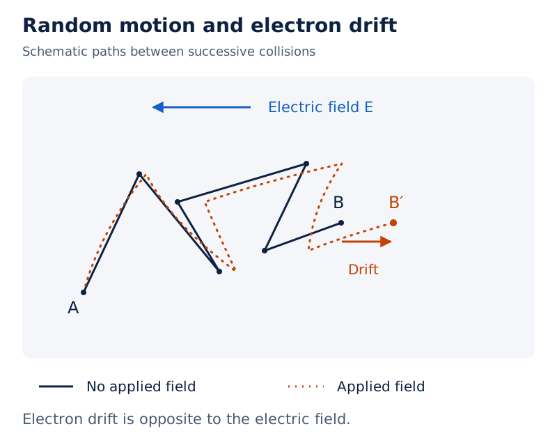
A solid zigzag path connects to , while a dotted path ends at , farther to the right. The electric-field arrow points left, opposite the small displacement of the endpoint.
Drawn by One Young India. See Fig. 3.3 in your NCERT textbook
The drawing is schematic. In the presence of a field, an electron’s path between collisions is generally curved because it accelerates. Without a field, the paths between collisions are straight.
How are mobility, current density and drift speed related?
What does mobility measure?
Mobility is the magnitude of drift velocity per unit electric field. It is positive, even though an electron’s drift velocity points opposite to the field. For electrons in the collision model, it depends on relaxation time and electron mass.
The SI unit of mobility is . For uniform current across a normal cross-section, . The relations and express the same ohmic behaviour using quantities inside the material.
Worked example 2. A copper wire carries through an area of . Copper density is , and atoms have mass . Assume one conduction electron per atom.
Formula: , where is the number of conduction electrons in a sample of volume , and , where here denotes speed.
- Substitute: Convert the given atomic mass information into mass per atom:
- Calculate electrons per unit volume:
- Use the electron charge magnitude:
- Evaluate the speed:
Answer: The drift speed is about , directed opposite to the field.
Why does a circuit respond so quickly?
A small drift speed does not imply a long delay before current appears throughout a circuit. The field is established rapidly and produces local drift at different points. Electrons need not travel from one end of the wire to the other first.
Substantial currents are possible because the carrier number density is enormous. Also, drift describes an average: individual electrons continue to have random velocities in many directions while the net charge transport has a definite direction.
When does Ohm’s law fail, and how do materials differ?
What features make a voltage-current graph non-ohmic?
Ohm’s law describes many materials over a suitable range, but it is not a universal law for every conducting device. A graph must be interpreted with attention to its axes, the direction of the applied voltage and the range being considered.
| Departure | What changes? | Illustration |
|---|---|---|
| Non-linear response | Voltage is no longer proportional to current | A conductor’s curve departs from a straight line |
| Dependence on voltage sign | Reversing voltage need not reverse an equal current | A diode has asymmetric behaviour |
| Non-unique relation | The same current can correspond to more than one voltage | Gallium arsenide shows such a characteristic |
What the figure shows
Non-ohmic characteristics
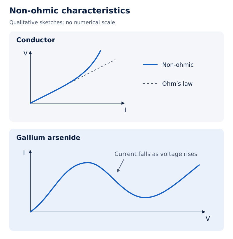
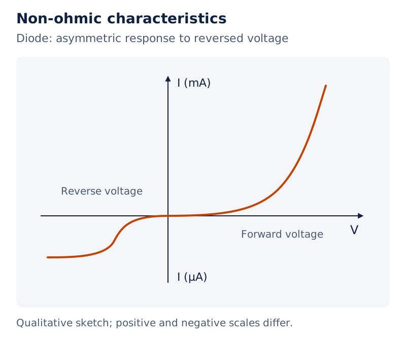
The voltage-current plot in Figure 3.5 shows a curved solid line departing from a dashed straight line. The diode plot uses unequal positive and negative scales. The gallium arsenide current-voltage curve rises, falls, then turns upwards again.
Drawn by One Young India. See Figs. 3.5 to 3.7 in your NCERT textbook
How does resistivity classify materials?
Conductors, semiconductors and insulators have broadly increasing resistivities. Metals typically lie in the range to . Rubber, plastics and ceramics have much larger resistivities, while semiconductors lie between metals and insulators.
The resistivity of a semiconductor decreases as temperature increases. Suitable small additions of impurities can also reduce semiconductor resistivity. Both temperature and composition therefore matter when comparing materials or interpreting measurements.
Note: A labelled resistance does not by itself establish ohmic behaviour. The test is whether the voltage-current ratio remains constant over the relevant range under unchanged physical conditions.
How does temperature change resistivity and resistance?
What is the linear temperature approximation?
Over a limited temperature range, a metal’s temperature coefficient of resistivity, , relates its resistivity to a chosen reference value. With temperatures and , the approximate relation is:
Here is resistivity at the reference temperature and is resistivity at the new temperature. The coefficient has units , or when the temperature difference is expressed in Celsius degrees.
For a resistance thermometer or a wire whose dimensional changes are neglected, let be its resistance at temperature and its resistance at the reference temperature . The corresponding working relation is . This approximation must not be extrapolated indiscriminately over all temperatures.
Why do metals and semiconductors behave differently?
In metals, electron density changes little with temperature, while a rise in temperature increases the average speed of the electrons, so collisions become more frequent and relaxation time decreases. Their resistivity therefore rises with temperature. In semiconductors and insulators, increased carrier density can more than compensate for the reduced relaxation time, so resistivity decreases.
Nichrome, manganin and constantan have relatively weak temperature dependence. They are useful in standard resistance wires because temperature changes alter their resistance values relatively little.
What the figure shows
Resistivity and temperature
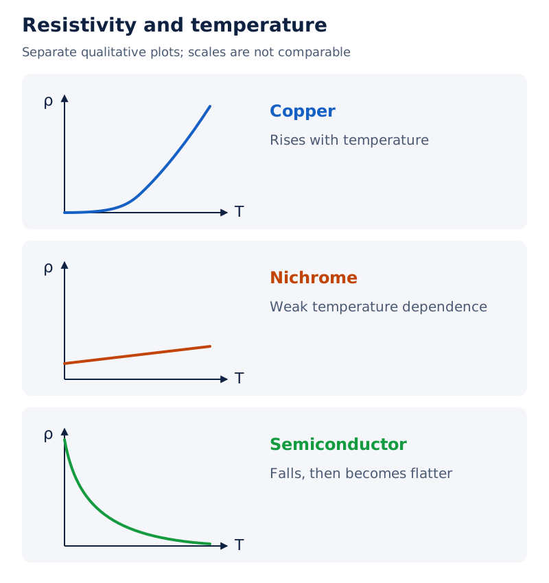
The copper curve rises with temperature and is curved at low temperatures. The nichrome plot rises gently. The semiconductor curve falls steeply at first and then becomes flatter.
Drawn by One Young India. See Figs. 3.8 to 3.10 in your NCERT textbook
Worked example 3. A platinum resistance thermometer reads at the ice point, at the steam point, and in a hot bath. Find the bath temperature using a linear calibration.
Formula: , and .
- Substitute: Find the resistance changes from the ice-point value:
- Use their ratio in the calibration:
Answer: The bath temperature is under the linear calibration.
Worked example 4. A silver wire has resistance at and at . Determine its temperature coefficient using the lower temperature as reference.
Formula: , so .
- Substitute: Calculate the changes:
- Evaluate the fractional resistance change per degree:
Answer: , referenced to .
How are electrical energy, heating and power related?
Derivation: power dissipated in a resistor
- A steady current carries charge through a resistor during a time interval:
- As this positive charge moves through potential difference , its electric potential energy decreases:
- Collisions transfer the energy gained by the carriers to the material, giving heat:
- Divide by time to obtain the dissipated power:
- For an ohmic resistor, substitute the voltage-current relation:
Result: The source supplies energy that is dissipated in the resistor. Carriers maintain a steady average drift instead of accumulating kinetic energy indefinitely.
The SI unit of power is the watt, , and the SI unit of energy is the joule, . Thus . In these formulas, voltage, current and resistance are in volts, amperes and ohms.
Why is high voltage used for power transmission?
Transmission cables have a finite resistance, so some supplied energy heats the cables. For a specified delivered power, increasing the transmission voltage reduces current. This reduces the ohmic loss in the wires.
- Express the current for delivered power and voltage :
- For cable resistance , write the power loss:
- Substitute the required current:
For fixed delivered power and cable resistance, the loss is inversely proportional to the square of the voltage. A transformer lowers the voltage at the receiving end to a value suitable for use.
When comparing resistor heating, specify what is fixed. At a fixed current, a larger resistance dissipates more power. At a fixed voltage, a larger resistance dissipates less power. These conclusions use different operating conditions and do not contradict one another.
What are emf, terminal voltage and internal resistance?
How does a cell supply energy?
A cell has positive and negative electrodes immersed in an electrolyte. Chemical processes supply the energy needed to maintain a current. Electromotive force, , is the work supplied per unit charge in moving charge from lower to higher potential energy within the source.
The SI unit of emf is the volt, , with . Despite its name, emf is not a mechanical force. It equals the potential difference across the cell’s terminals when no current flows.
The electrolyte offers an internal resistance, , measured in ohms. When the cell delivers current, the terminal voltage is smaller than its emf because of the internal voltage drop.
What the figure shows
Electrolytic cell and external resistor
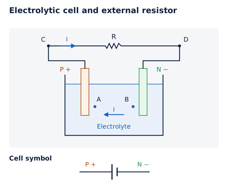
Electrodes and stand in an electrolyte, with points and close to them. The external circuit links them through resistor , between and . A second sketch shows the cell symbol.
Drawn by One Young India. See Fig. 3.12 in your NCERT textbook
Derivation: current delivered to an external resistor
- For current leaving the positive terminal, write the terminal voltage:
- The same voltage appears across the external resistance:
- Equate and collect the resistance terms:
- Solve for current and terminal voltage:
Result: Both external and internal resistance limit the current. Internal resistance can be neglected only when the internal voltage drop is small compared with the emf.
For , the model gives . This is a limiting current, not generally an acceptable operating current: excessive current can permanently damage a cell.
Worked example 5. A battery of emf and internal resistance supplies through an external resistor. Find that resistance and the terminal voltage.
Formula: , and .
- Substitute: Calculate the external resistance:
- Calculate the terminal voltage:
- Check across the external resistor:
Answer: The resistor is , and the terminal voltage is .
What changes when a battery is charged?
When an external supply drives current into the positive terminal, the terminal voltage is . Current direction through the cell determines the sign; the internal resistance itself remains positive.
Worked example 6. An storage battery with internal resistance is charged from a supply through a series resistor. Find its terminal voltage.
Formula: , and , where is the external supply voltage and is the battery terminal voltage.
- Substitute: The supply must overcome the battery emf:
- Add the internal voltage drop to the emf:
- Check against the external resistor’s drop:
Answer: The charging terminal voltage is . The series resistor limits the charging current.
How are cells combined in series and parallel?
How do series cells combine?
Cells can be replaced, for external circuit calculations, by an equivalent cell having an equivalent emf and internal resistance. In a series connection, the same current passes through the cells. Their terminal potential differences add algebraically.
- For two cells connected with aiding polarities, let be their emfs and their internal resistances, respectively. Let , , and , where are the potentials at the three connection points. Write their terminal voltages:
- Add the potential differences:
- Compare with the single-cell form to identify the equivalent quantities:
If one cell is reversed, its emf enters with the opposite sign. For opposing cells with , the equivalent emf is . Internal resistances still add.
What the figure shows
Series cells
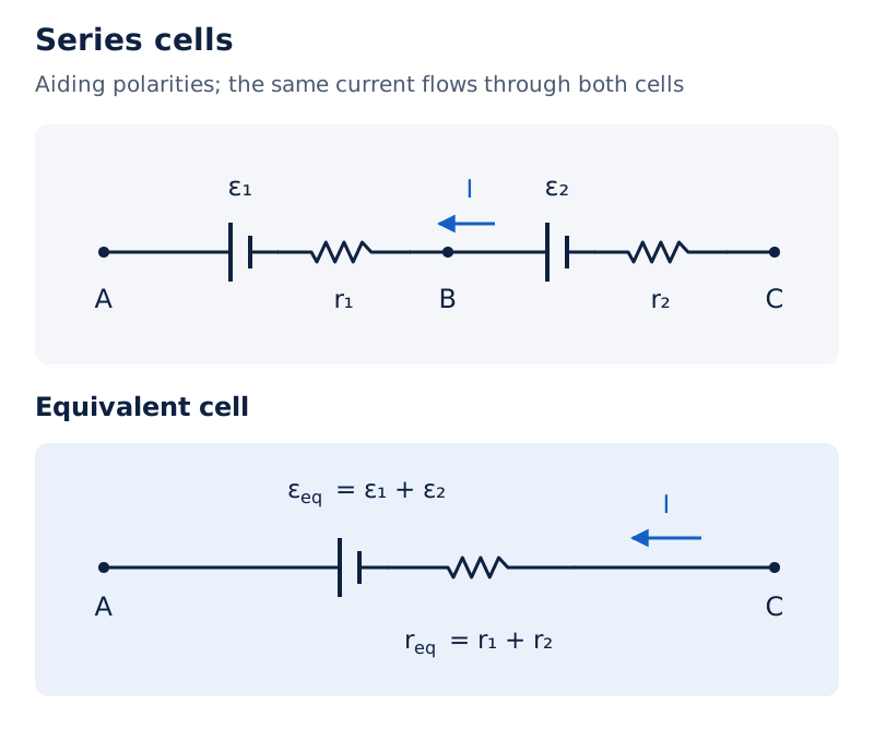
Two cells lie along the path from , through , to , carrying the same labelled current. Beside them is the replacement cell labelled with equivalent emf and internal resistance.
Drawn by One Young India. See Fig. 3.13 in your NCERT textbook
How do parallel cells combine?
In parallel, like terminals are joined together. Both branches have the same terminal voltage, while the external current is the algebraic sum of the branch currents. With finite internal resistances, the branch equations determine the equivalent source.
- Let be the currents leaving the positive terminals of the two cells, and the external current. Write the two cell equations at common voltage :
- Add branch currents at the junction:
- Compare with :
For several similarly connected cells, and . A reversed cell contributes a negative emf term. Emfs are in volts and all internal resistances are in ohms.
Note: Parallel emfs are not generally added or averaged arithmetically. The equivalent emf is weighted by the reciprocal internal resistances, as the branch equations show.
How do Kirchhoff’s rules solve a circuit?
What does each rule conserve?
Kirchhoff’s junction rule expresses charge conservation in a steady circuit. Charge does not accumulate at a junction, so the total current entering equals the total current leaving. The rule also applies at a point along an unbranched wire.
Kirchhoff’s loop rule states that the algebraic sum of potential changes around a closed loop is zero. Returning to the starting point returns to the same potential; the accumulated rise and fall must therefore cancel.
How are signs assigned consistently?
| Element crossed | Traversal direction | Potential change |
|---|---|---|
| Resistor | Along its assigned current | |
| Resistor | Opposite its assigned current | |
| Ideal emf | Negative to positive terminal | |
| Ideal emf | Positive to negative terminal |
For a real cell, include its internal resistance as well as its emf. Do not use the terminal voltage of a discharging cell when the assigned current instead enters its positive terminal.
- Label source polarities and choose an arrow for each unknown branch current. The initial arrows are assumptions, not claims that the direction is already known.
- Apply the junction rule to express dependent branch currents in terms of a smaller set of unknowns.
- Choose closed loops and write potential changes in a consistent traversal direction, including resistance and emf terms.
- Solve enough independent equations for the unknown currents. A negative result means the actual current flows opposite to its assigned arrow.
- Check the results in another junction or loop equation. Extra loop equations may repeat information rather than supply independent constraints.
These rules are especially useful for networks that cannot be reduced by simple resistance combinations. Symmetry, when present, can reduce the number of unknown currents, but a general network requires the junction and loop equations themselves.
How does a Wheatstone bridge determine an unknown resistance?
What is the balanced condition?
A Wheatstone bridge has four resistors arranged in four arms. The source is connected across one diagonal and a galvanometer across the other. The galvanometer detects current; it is used here to identify a zero-current, or null, condition.
What the figure shows
Wheatstone bridge arrangement
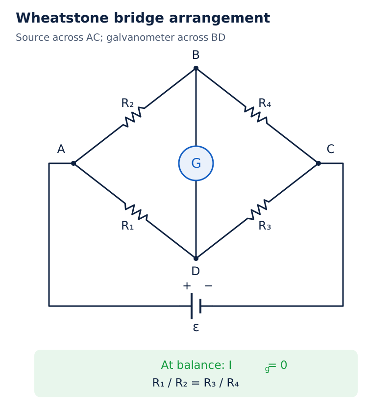
The diamond has vertices at left, above, at right and below. Resistors , , and occupy , , and , respectively. The galvanometer joins to ; the cell connects across and .
Drawn by One Young India. See Fig. 3.18 in your NCERT textbook
Derivation: Wheatstone bridge balance
- Let be the galvanometer current, and let flow along , respectively. At balance, the galvanometer carries no current: Junction continuity then gives and .
- The galvanometer terminals have equal potential. The loop through the two left arms gives:
- The loop through the right arms gives:
- Divide the two relations to eliminate currents:
- If the fourth arm is unknown, rearrange:
Result: Keep the first two resistances known and vary the third until the galvanometer shows null deflection. The balance relation then determines the unknown resistance. A metre bridge is a practical device based on this principle.
What if the galvanometer current is not zero?
The balance ratio cannot be applied to an unbalanced bridge. Current then flows through the galvanometer arm, and its resistance must be included in the loop equations. The currents through adjacent arms need not be equal.
Worked example 7. A bridge has , , , , and a galvanometer across . A supply is connected with its positive terminal at and negative terminal at . Find the magnitude and direction of the galvanometer current. Let flow from to , from to , and from to .
Formula: Apply the junction and loop rules; the bridge is not balanced.
- Substitute: The loop through , and gives:
- The junction rule gives from to and from to . The loop through , and then gives:
- The supply loop through and gives:
- Subtract ten times the second equation from the first, then rearrange:
- Insert this result into the supply loop:
- Evaluate the galvanometer current:
Answer: The current is , flowing from to .
Glossary
- Electric current — Net charge passing through a specified cross-section per unit time, with direction represented by an algebraic sign.
- Current density — Vector describing current per unit normal area, directed along conventional positive charge flow.
- Resistance — Ratio of potential difference to current for a conductor at the operating point considered.
- Resistivity — Material property connecting resistance with length and cross-sectional area, dependent on conditions such as temperature.
- Conductivity — Reciprocal of resistivity, relating current density to electric field in an ohmic material.
- Drift velocity — Average directed velocity acquired by mobile charge carriers under an applied electric field.
- Relaxation time — Average time between successive collisions of conduction electrons in the collision model of a metal.
- Mobility — Positive ratio of the magnitude of carrier drift velocity to the applied electric field.
- Temperature coefficient — Fractional resistivity increase per unit temperature increase within a range where the dependence is approximately linear.
- Electromotive force — Energy supplied per unit charge by a source, equal to its open-circuit terminal potential difference.
- Internal resistance — Resistance within a cell that contributes to its internal voltage drop when current flows.
- Terminal voltage — Potential difference between a source’s terminals under the circuit conditions being considered.
- Galvanometer — Device that detects current and identifies the null condition in a balanced Wheatstone bridge.
- Balanced bridge — Wheatstone bridge condition in which no current passes through the galvanometer joining the intermediate junctions.
Common errors and misconceptions
- Misconception: Current is a vector because circuit diagrams show arrows. Correct: Current is scalar; its arrow establishes a sign convention. Current density is vectorial.
- Misconception: All electrons move along the drift direction. Correct: Drift is a small average superposed on random electron velocities pointing in many directions.
- Misconception: Writing proves that a device obeys Ohm’s law. Correct: Ohmic behaviour also requires resistance to be independent of voltage within the specified range and conditions.
- Misconception: Resistance and resistivity both increase when a wire becomes longer. Correct: For the same material and conditions, length affects resistance, while resistivity is independent of dimensions.
- Misconception: Every material’s resistivity increases with temperature. Correct: Metals generally show an increase, while semiconductors show a decrease as carrier density rises.
- Misconception: Emf is a force and always equals terminal voltage. Correct: Emf is energy per unit charge. Internal resistance makes the terminal voltage depend on current and its direction.
- Misconception: A negative circuit current is an impossible answer. Correct: It means the actual current direction is opposite to the arrow initially assumed.
- Misconception: The bridge ratio applies even when the galvanometer carries current. Correct: The balance relation requires zero galvanometer current; otherwise include that branch in Kirchhoff’s equations.
Exam-style questions with model answers
Q1. Define electric current and state its SI unit. [2 marks]
- Electric current is the net charge crossing a specified area per unit time. For steady flow, .
- Its SI unit is the ampere, with . A negative current indicates flow opposite to the chosen positive direction.
Q2. Distinguish resistance from resistivity and explain the role of dimensions. [3 marks]
- Resistance belongs to a particular conductor and depends on its material, length and cross-sectional area. Resistivity characterises the material at specified physical conditions.
- For a uniform conductor, . Increasing length increases resistance, while increasing cross-sectional area decreases it, provided material and temperature remain unchanged.
- Resistance is measured in ohms; resistivity is measured in ohm metres. Changing dimensions alone does not change the material’s resistivity.
Q3. Derive the conductivity of a metal using electron drift. State the assumptions. [5 marks]
- Let the electron charge be , mass , carrier number density and average collision time . In an electric field, electron acceleration is .
- Post-collision velocities are random and average to zero. Averaging the field-produced velocity over the collision time gives . Electron drift is opposite to the field.
- During , the electron number crossing normal area is . Hence the current magnitude is .
- Current density follows by dividing by area: . Conventional current density is along the field, despite the opposite electron drift.
- Comparison with gives and . The model assumes that carrier density and relaxation time are independent of the applied field.
Q4. Explain why a metal’s resistivity usually rises with temperature, while a semiconductor’s falls. [3 marks]
- The collision model gives . Resistivity therefore depends on both carrier number density and the mean time between collisions.
- In a metal, carrier density changes little with temperature. A rise in temperature increases the average speed of the electrons, so collisions become more frequent and the relaxation time decreases. Hence resistivity increases.
- In a semiconductor, increasing temperature raises the number of available carriers. This increase can more than compensate for the decrease in relaxation time, causing the resistivity to fall instead.
Q5. Distinguish emf from terminal voltage for a discharging cell. [2 marks]
- Emf is the energy supplied per unit charge and equals the open-circuit terminal voltage.
- Terminal voltage is the potential difference between the cell's terminals when it supplies current . Because of the internal resistance , it is less than the emf: . Both emf and terminal voltage are measured in volts.
Q6. State Kirchhoff’s rules and explain how current directions are handled when solving a network. [4 marks]
- The junction rule states that total incoming current equals total outgoing current. It follows from charge conservation and the absence of charge accumulation in a steady circuit.
- The loop rule states that potential changes sum to zero around a closed path, because the path returns to its starting potential.
- Assign branch-current arrows, apply junction equations, and form independent loop equations. Crossing a resistor along its assumed current gives a potential drop.
- Solve the equations algebraically. A negative value means the actual current flows opposite to the assigned direction; it does not invalidate the method.
Q7. Derive the Wheatstone bridge balance condition and explain how it measures an unknown resistance. [5 marks]
- Connect four arms between vertices , with the source across and galvanometer across . Let occupy , respectively.
- At balance, the galvanometer current , so junction continuity gives equal currents in the two successive resistors of each outer branch: let flow through and , and through and . The galvanometer’s endpoints have equal potential.
- Apply the loop rule to the left pair of arms: . Apply it to the right pair: .
- Divide these equations to eliminate the currents: . Equivalently, the balance condition is .
- With the first two resistances known, vary the third until null deflection is obtained. The fourth, unknown resistance is then . This measurement requires a balanced bridge; the ratio cannot replace the full circuit equations when galvanometer current is non-zero.
Key takeaways
- Electric current measures net charge flow, while electron drift is a small directed average superposed on random motion.
- Ohm’s law requires a constant voltage-current ratio under the specified physical conditions and within the applicable field range.
- Resistance depends on a conductor’s dimensions, whereas resistivity is a material property affected by temperature and other conditions.
- The drift model connects conductivity with carrier density and relaxation time, explaining how microscopic collisions affect electrical conduction.
- Metals and semiconductors respond differently to heating because temperature changes their carrier densities and collision times differently.
- A cell’s terminal voltage depends on internal resistance and on whether the current leaves or enters its positive terminal.
- Kirchhoff’s rules combine charge continuity at junctions with zero total potential change around a closed circuit loop.
- A Wheatstone bridge measures an unknown resistance through a null condition, with no current through its galvanometer arm.
Test yourself
Why is there no net current from random electron motion alone?
There is no preferred direction, so velocities and charge flows in opposite directions cancel on average.
What is the direction of electron drift relative to the electric field?
Electron drift is opposite to the field because an electron carries negative electric charge.
Why does slow drift not imply a long delay when a circuit is closed?
The field is established rapidly throughout the circuit, producing local drift without waiting for electrons to traverse the entire wire.
What does mobility measure, and can it be negative?
Mobility is drift-speed magnitude per unit electric field; it is positive even for negatively charged carriers.
When does a cell’s terminal voltage equal its emf?
In an open circuit, no current flows and there is no internal resistive voltage drop.
What does a negative solution for an assumed branch current mean?
The current’s actual direction is opposite to the arrow chosen when setting up the equations.
Why are high transmission voltages useful for a fixed delivered power?
Higher voltage requires less current, reducing the power dissipated as heat in the transmission cables.
What observation identifies balance in a Wheatstone bridge?
The galvanometer shows null deflection, indicating zero current through the branch between its two terminals.