
Electromagnetism | ICSE Class 10 Physics Notes
On this page
Watch & explore
Start with a few high-quality watches, then dive into the notes below.
This note covers the magnetic effect of current, magnetic field lines, straight conductors, circular loops, solenoids, electromagnets, magnetic force, direct current motors, electromagnetic induction, alternating current generators, alternating and direct current, and transformers.
How does Oersted’s experiment connect electricity and magnetism?
Electric current is the rate of flow of electric charge. A conductor is a material through which electric charge can flow. A current through a metallic conductor produces a magnetic effect in the region around it. The SI unit of current is the ampere, symbol A; SI means International System of Units.
A compass contains a small magnetic needle. Its ends point approximately towards north and south when it is free to turn. Its north-seeking end is the north pole, and its south-seeking end is the south pole. Like magnetic poles repel; unlike poles attract.
What is observed when current flows?
- Place a straight copper wire parallel to and above a compass needle. Connect the wire to a cell, a source of electrical energy, through a key, which is a switch for opening or closing the circuit.
- Close the key so that the circuit provides a complete conducting path and current flows through the wire.
- Observe the needle turning away from its original position. This change in direction is called a deflection.
- Reverse the cell connections. The current reverses, and the compass needle deflects in the opposite direction.
This is Oersted’s experiment. The compass responds because the current produces a magnetic field. Reversing the current reverses the direction of this field. Conventional current direction is the direction in which positive charge would flow; in the external circuit it runs from the cell’s positive terminal to its negative terminal. The observation connects an electrical cause, current in the wire, with a magnetic effect, deflection of the needle.
The compass detects the field around the wire; it does not have to touch the wire. The direction of its deflection depends on both the direction of current and the position of the compass relative to the conductor.
What do magnetic field lines tell us?
Definition: A magnetic field is the region around a magnet in which its magnetic force can be detected. Magnetic field also describes a quantity with both magnitude, meaning size, and direction; its symbol is B.
The SI unit of magnetic field is the tesla, symbol T. Magnetic field lines are lines used to represent the direction and relative strength of the field. At a point, the direction is that indicated by the north pole of a small compass needle.
How should a field pattern be read?
Outside a bar magnet, field lines emerge from the north pole and enter the south pole. Inside the magnet, their direction is from south to north. Thus, the lines form closed curves; they do not simply stop at a pole.
Closer field lines represent a stronger field. Where the lines are more widely separated, the field is weaker. Parallel, equally spaced lines represent a uniform magnetic field, which has the same magnitude and direction throughout the region represented.
Two magnetic field lines do not intersect. An intersection would require the compass needle at that point to indicate two different field directions. There is a single direction for the resultant field, meaning the combined field, at a point where that field is non-zero.
How can the pattern be traced?
Iron filings sprinkled around a magnet arrange themselves along its field pattern when the supporting board is tapped gently. A compass can then supply the direction. Move it step by step, marking the needle positions and joining the marks with a smooth curve.
The filings reveal the pattern, while compass observations establish the arrows. A drawing needs both the shapes of the lines and their directions to represent the magnetic field clearly.
How is the field around a straight current-carrying wire found?
A straight wire carrying current produces field lines that form concentric circles, meaning circles with a common centre, around the wire. These circles lie in planes perpendicular to the wire. Perpendicular directions meet at a right angle.
What does the right-hand thumb rule state?
Imagine holding the straight conductor in your right hand. Point the thumb along the current. The curled fingers show the direction of the magnetic field lines around the conductor. This is the right-hand thumb rule.
Keep the direction along the wire separate from the direction around it. The thumb represents current, and the fingers represent the surrounding field. Reversing the current reverses the field arrows, while the circular pattern remains centred on the conductor.
A battery supplies electrical energy. An ammeter measures current. A rheostat is a variable resistance used to alter current; resistance is the opposition offered to current. These components allow the field to be studied while changing the current in a controlled way.
What the figure shows
Field around a straight conductor
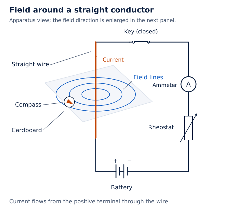
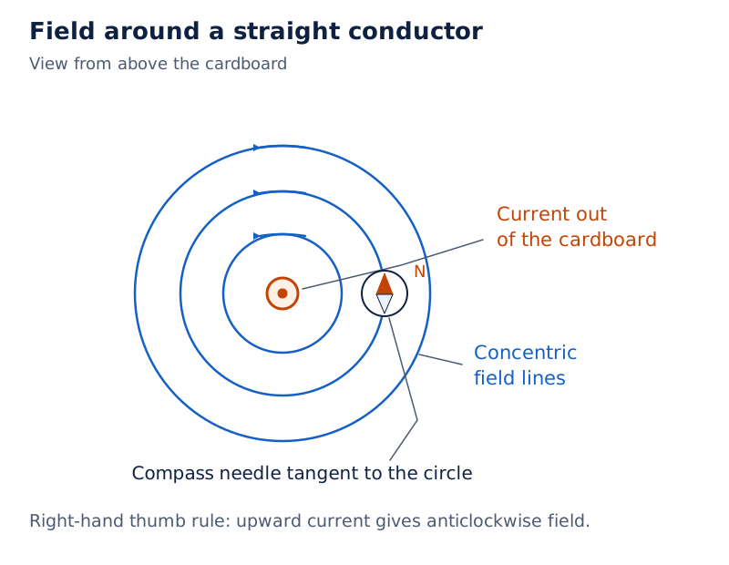
The circuit drawing shows a vertical wire through a cardboard sheet, circular field lines, a compass, a battery, a key, a current-measuring instrument and a variable resistance. Photograph: Figure 12.6(b), captioned “A close up of the pattern obtained”, shows iron filings arranged in circles around the straight wire.
Drawn by One Young India.
What changes the field strength?
| Change made | Condition kept fixed | Result |
|---|---|---|
| Increase the current | Position of the compass | The magnetic field becomes stronger and compass deflection increases. |
| Move farther from the wire | Current through the wire | The magnetic field becomes weaker and compass deflection decreases. |
| Reverse the current | Wire and compass positions | The direction of the magnetic field reverses. |
For a fair comparison of strength at different distances, the current remains the same. For a comparison using different currents, keep the observation point fixed. Otherwise, changing both factors makes it difficult to identify the cause of the observed difference.
How does a circular current-carrying loop produce a magnetic field?
A circular loop is a conductor bent into a circle. Current in each small part of the loop contributes to the magnetic field. Near the wire, the field lines curve around it. Towards the centre, the arcs appear as straight lines.
Apply the right-hand thumb rule to different parts of the loop. The contributions within the loop point in the same direction, so they reinforce one another. The field at the centre is perpendicular to the plane of the loop, meaning the flat surface containing it.
How are the two faces distinguished?
Viewed from one face, an anticlockwise current makes that face behave as a north pole. The opposite face then behaves as a south pole, and current viewed from that opposite side appears clockwise. State the viewing face when describing clockwise or anticlockwise current.
Field lines emerge from the north face and enter the south face. This connects the current direction with the familiar bar-magnet pattern. Reversing the current reverses the magnetic polarity, meaning which face is north and which is south.
What happens when the number of turns increases?
A coil consists of turns of conducting wire. For closely placed circular turns carrying the same current in the same direction, the field contributions add. A coil with more such turns produces a stronger field than a single turn.
The number of turns and the current are different factors. Increasing the current strengthens the field of a given coil. Increasing the number of matching turns strengthens the combined field because each turn contributes in the same direction.
What is a solenoid, and how does it become an electromagnet?
Definition: A solenoid is a coil of many closely wound circular turns of insulated copper wire arranged in the shape of a cylinder. Insulation is a covering that prevents electrical contact between neighbouring turns.
The magnetic field around a current-carrying solenoid resembles that around a bar magnet. One end behaves as a north pole and the other as a south pole. Reversing the current exchanges the poles, just as reversing current changes the field direction around a loop.
What is the field inside the coil like?
Inside a long solenoid, the field is represented by parallel straight lines and is treated as uniform. The lines spread out near and beyond the ends, where the field becomes weaker. The interior pattern and the spreading end pattern should be distinguished.
What the figure shows
Field through a solenoid
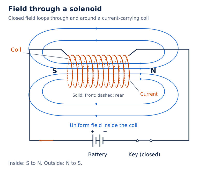
A closely wound coil is connected to a battery and key. Field lines pass through the coil and curve around outside it. Arrows show their directions, forming loops through and around the solenoid.
Drawn by One Young India.
What does a soft-iron core do?
A core is material placed inside a coil. The strong field of a solenoid can magnetise soft iron placed inside it. To magnetise a material means to make it behave as a magnet. This arrangement forms an electromagnet.
An electromagnet therefore combines a current-carrying coil with a magnetic core. The coil produces the magnetising field, and the soft iron becomes magnetic in that field. Switching off the current removes the coil’s magnetising action.
How do electromagnets and permanent magnets differ?
A permanent magnet retains its magnetisation for a long period after the magnetising field has been removed. Some magnetic materials retain this magnetisation, whereas soft iron loses its magnetisation when the external magnetising field is removed. This distinction explains their different uses.
Which properties can be controlled?
| Feature | Soft-iron electromagnet | Permanent magnet |
|---|---|---|
| Source of its magnetising field during use | Current in the surrounding coil | Retained magnetisation of the material |
| Dependence on current | The coil must carry current to maintain its magnetising action. | No continuous electric current supply is needed to maintain its magnetism. |
| Control of strength | Changing the coil current changes the magnetic field. | Its strength is not controlled by a supply current during ordinary use. |
| Control of poles | Reversing current exchanges the north and south poles. | There is no supply-current reversal for changing its poles during ordinary use. |
| Useful behaviour | Provides a field associated with a controllable current. | Provides a persistent magnetic field. |
The comparison concerns a soft-iron electromagnet. It should not be extended to every rod inserted into a coil. A suitable material such as steel can retain magnetism after magnetisation; the behaviour depends on the core material.
Where are these magnets used?
Commercial electric motors use electromagnets in place of the permanent magnets shown in a simple motor model. They also use many turns of conducting wire and a soft-iron core. A motor is a device that converts electrical energy into mechanical energy, the energy associated with motion or position.
Electromagnets are also used in generators, devices that convert mechanical energy into electrical energy. In most generators, the coils are stationary and the electromagnets rotate. A compass needle, by comparison, uses retained magnetism to respond to the surrounding magnetic field.
How does a magnetic field exert force on a current-carrying conductor?
A current-carrying conductor placed in a magnetic field can experience a force, a push or pull. The SI unit of force is the newton, symbol N. Here N is a unit symbol; on magnet diagrams, the label N instead identifies the north pole.
Suspend an aluminium rod between the poles of a magnet and pass current through it. The rod is displaced. Reversing the current reverses its displacement. Reversing the magnetic field while keeping the current direction unchanged also reverses the force.
When is the force greatest?
The force is greatest when current is perpendicular to the magnetic field, with other factors unchanged. In this arrangement, the force acts perpendicular to both the current and the field. The three directions can be represented by three mutually perpendicular fingers.
- Stretch the thumb, forefinger and middle finger of the left hand so that all three are mutually perpendicular.
- Point the forefinger in the direction of the magnetic field, from the north pole towards the south pole in the gap between the poles.
- Point the middle finger in the direction of the current through the conductor.
- The thumb then gives the direction of the force or resulting motion of the conductor.
This is Fleming’s left-hand rule. The current and magnetic field are the given directions; the force is the direction found. The rule describes the direction of the motor effect, the force effect used to produce motion in an electric motor.
Note: The right-hand thumb rule finds the field produced around a current-carrying wire. Fleming’s left-hand rule finds the force on a current-carrying conductor in an external magnetic field. Their fingers represent different quantities.
What are the main parts and energy transfer of a direct current motor?
Direct current, abbreviated DC, flows in one direction. A simple DC electric motor uses the force on a current-carrying coil placed in a magnetic field. Its energy transfer is from electrical energy to mechanical energy.
Which parts belong in a labelled sketch?
| Part | Description or role |
|---|---|
| Coil | A rectangular conducting loop placed between magnetic poles and able to rotate. |
| Magnet | Provides the magnetic field in which the coil carries current. |
| Split-ring commutator | A conducting ring divided into two insulated halves, connected to the coil ends. |
| Brushes | Stationary conducting contacts connected to the battery and touching the split-ring halves. |
| Axle | The shaft about which the coil and split-ring assembly rotate. |
A commutator is a device that reverses the current connection to the coil. The split-ring commutator has two separate halves, not two complete rings. Brushes provide contact between the external circuit and the rotating assembly.
Diagram
Main parts of a DC motor
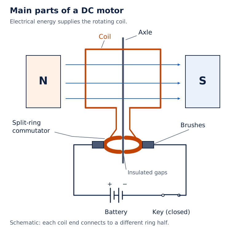
Draw a rectangular coil between a north pole and a south pole. Connect its ends to separate halves of a split ring on an axle. Show two stationary brushes touching the halves and connected to a battery through a key.
Drawn by One Young India.
Label the coil, magnet, split-ring commutator, brushes, axle and battery. North and south labels belong on the magnetic poles. The battery shows that electrical energy is supplied to the device; rotation of the coil represents mechanical output.
Electric fans, mixers, washing machines and computer drives use motors. These applications share the same energy conversion even though their mechanical tasks differ. The motor’s magnetic field enables the force effect; the electrical supply provides the energy that is converted.
What is electromagnetic induction?
Definition: Electromagnetic induction is the production of an induced voltage when the magnetic field linked with a conductor or coil changes. If the conducting circuit is closed, an induced current can flow.
Voltage, or potential difference, measures energy transferred per unit charge between two points. The SI unit of potential difference is the volt, symbol V. Induced means produced by the changing magnetic conditions, rather than supplied directly by a cell connected to that coil.
What happens when a magnet moves near a coil?
Connect a coil to a galvanometer, a sensitive instrument that detects small electric currents and their direction. Move a bar magnet towards the coil, stop it, and then withdraw it. The observations reveal when induction occurs.
| Action | Galvanometer observation | Conclusion |
|---|---|---|
| Push the north pole towards the coil | The pointer deflects. | A current is induced while the magnet moves. |
| Hold the magnet stationary relative to the coil | The pointer shows no deflection. | A stationary magnet in this arrangement does not maintain induced current. |
| Withdraw the same pole | The pointer deflects in the opposite direction. | The induced current reverses. |
| Move the same pole faster | The deflection is larger. | The induced current is greater. |
Moving the coil while holding the magnet fixed produces the same kind of effect. What matters in this experiment is relative motion, meaning a change in the position of the magnet with respect to the coil.
What the figure shows
Magnet approaching a coil
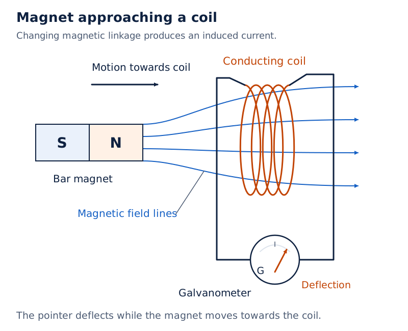
A bar magnet is shown with its north pole facing a conducting coil. An arrow indicates motion towards the coil. The coil is connected to a galvanometer, and blue magnetic field lines pass through it.
Drawn by One Young India.
How are changing flux and induced voltage calculated?
Magnetic flux measures the magnetic field passing through an area. For a uniform field, , where is magnetic field strength in tesla (T), is area in square metres (m²), and is the angle between the field and the normal to the area.
The SI unit of magnetic flux is the weber, symbol Wb. For a single loop with a steady flux change, the induced voltage magnitude is . Here is the flux change in Wb, is the elapsed time in seconds, and is in volts.
For a closed loop of resistance in ohms, the induced current magnitude is , in amperes. These magnitude equations do not specify polarity; the induced current opposes the change in magnetic flux that produces it.
Worked example 1. A square loop of side 10 cm and resistance 0.5 Ω lies vertically in the east-west plane. A uniform field of 0.10 T directed north-east decreases steadily to zero in 0.70 s. Find the induced voltage and current magnitudes.
Answer: The field makes an angle of 45° with the normal to the loop. Convert the side to 0.10 m, giving an area of 0.010 m².
Formula: , , and .
Substitute: . The final flux is zero, so .
Then . To two significant figures, the voltage is 0.0010 V and the current is 0.0020 A.
Derivation: How does a moving rod develop a voltage?
A conducting rod of length slides at constant speed along a rectangular circuit in a uniform field . The field is perpendicular to the circuit, and the rod moves perpendicular to its own length. Consider voltage magnitudes.
- For the enclosed width , the area is . The magnetic flux is therefore .
- During time , the width changes by magnitude . With field and rod length constant, .
- Divide the flux change by the elapsed time: .
Result: for this perpendicular arrangement. With in T, in m and in m/s, the induced voltage is in V. A complete conducting path is needed for a sustained induced current.
Worked example 2. A rectangular loop measuring 8 cm by 2 cm has a small cut. It moves out of a uniform 0.3 T field normal to its plane at 1 cm/s. Find the voltage across the cut and its duration for motion perpendicular to each side.
Answer: Convert the dimensions to 0.08 m and 0.02 m, and the speed to 0.01 m/s. The effective length is the side crossing the field boundary; is the distance travelled while the loop leaves the field.
Formula: and .
Substitute: For motion perpendicular to the longer side, , and .
For motion perpendicular to the shorter side, , and . Thus the voltages are 0.00024 V for 2 s and 0.000060 V for 8 s, respectively.
Worked example 3. A horizontal wire 10 m long extends from east to west and falls at 5.0 m/s, perpendicular to the horizontal component of Earth’s magnetic field, 0.30 × 10⁻⁴ T. Find the instantaneous induced voltage and identify the end at higher potential.
Answer: Formula: . Substitute: . The voltage is 0.0015 V.
Point the right-hand forefinger north along the horizontal field and the thumb downwards along the motion. The middle finger points east. The induced emf acts from west to east, so the eastern end is at the higher potential.
Must a coil physically move for induction to occur?
No. In two stationary neighbouring coils, switching the current in one coil on or off changes its field. This produces a momentary current in the other closed coil. Maintaining a steady current in the first coil does not maintain that induced current.
The essential idea is therefore change in the linked magnetic field. Motion is one way to produce this change; changing the current in a nearby coil is another. A magnetic field being present is not, by itself, enough.
How are the induced-current direction and an alternating current generator described?
Fleming’s right-hand rule gives the direction of induced current when a conductor moves across a magnetic field. Stretch the thumb, forefinger and middle finger of the right hand so that they are mutually perpendicular.
- Use the forefinger to represent the direction of the magnetic field.
- Use the thumb to represent the direction in which the conductor moves.
- The middle finger gives the direction of the induced current in a closed circuit.
- Keep this assignment separate from the left-hand rule, where current is supplied and force is the result being found.
What does a simple generator contain?
Alternating current, abbreviated AC, reverses direction periodically. An AC generator converts mechanical energy into electrical energy by electromagnetic induction. In the simple model, a coil is rotated mechanically between magnetic poles.
The rotating coil is called the armature and is mounted on a shaft. Its ends connect to two slip rings, separate complete conducting rings that rotate with the coil. Stationary brushes touch the rings and connect the coil to the external circuit.
What the figure shows
Simple AC generator
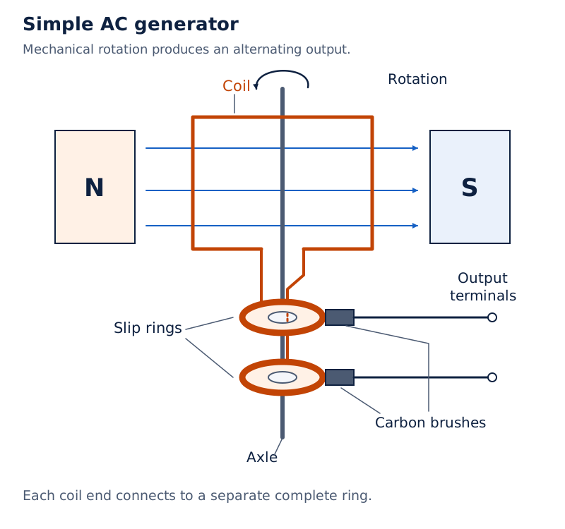
The drawing shows a coil between north and south magnetic poles. It labels the coil, axle, slip rings and carbon brushes. The two brushes connect to output terminals, and an arrow indicates rotation.
Drawn by One Young India.
The mechanical input changes the magnetic field linkage as the coil turns. The resulting output is alternating. The generator does not create energy: an external source must supply the mechanical energy that is converted into electrical energy.
How is the maximum generator voltage calculated?
For a coil rotating uniformly in a uniform magnetic field with its rotation axis perpendicular to the field, and . Here is rotation frequency in Hz, is angular speed in rad/s, and is the number of turns.
The field strength is in T and each turn has area in m². The maximum voltage is in V. The instantaneous voltage alternates as the coil rotates; the maximum value is its peak magnitude.
Worked example 4. Kamla pedals a stationary bicycle connected to a coil of 100 turns and area 0.10 m². It rotates at half a revolution per second in a uniform field of 0.01 T perpendicular to its rotation axis. Find the maximum generated voltage.
Answer: The frequency is 0.5 Hz. Formula: and .
Substitute: . Then . The maximum voltage is 0.314 V.
How does this differ from a motor?
A motor receives electrical energy and supplies mechanical energy. A generator receives mechanical energy and supplies electrical energy. The simple DC motor has a split-ring commutator, whereas the simple AC generator has two complete slip rings. Identifying the energy input and the ring arrangement distinguishes the two sketches.
How do alternating and direct current differ, and why is AC useful?
Direct current flows in one direction. Alternating current reverses direction periodically, meaning at repeating intervals. Do not describe DC merely as a current that must have a constant magnitude: the defining contrast here concerns its direction.
What does a frequency of 50 Hz mean?
Frequency is the number of complete cycles in one second. A cycle is one complete repetition of the alternating variation, including both directions. The SI unit of frequency is the hertz, symbol Hz. Household AC in India has a frequency of 50 Hz.
This means fifty complete cycles occur in one second. The current changes direction twice during each cycle, so it changes direction one hundred times per second. Counting direction changes is different from counting complete cycles.
Note: A frequency of 50 Hz means 50 complete cycles per second, not 50 direction reversals per second. Each complete alternating cycle includes two changes of direction.
How do effective and peak alternating values differ?
The root mean square (rms) current is the equivalent direct current producing the same average heating power in a resistor. For sinusoidal AC, the peak voltage is , where is the rms voltage, with both measured in volts.
For a resistive load, average power is and . Here is in watts, and are rms voltage and current in volts and amperes, and is resistance in ohms.
Worked example 5. A light bulb is rated at 100 W for a 220 V sinusoidal AC supply. Find its operating resistance, the peak supply voltage and the rms current.
Answer: Treat the bulb as a resistive load. Formula: , , and .
Substitute: . The peak voltage is . The rms current is .
The answers are 484 Ω, approximately 311 V and 0.455 A. The rated 220 V is the rms voltage, so it must not be mistaken for the peak value.
What advantage does AC offer in transmission?
AC voltages can be changed easily and efficiently by transformers, devices that raise or lower an alternating voltage. This makes economical transmission of electrical energy over long distances possible.
At the generating end, voltage is raised so that the same transmitted power, meaning energy transferred per second, can be carried with a lower current. The lower current reduces heating losses in the transmission wires. Near consumers, the voltage is reduced again for distribution and use.
This advantage concerns the ability to change voltage and reduce energy loss during transmission. The transformer does not supply extra energy merely because its output voltage is larger. Its voltage change must be considered alongside the corresponding change in current.
How do step-up and step-down transformers differ?
A transformer has two sets of coils insulated from one another and wound on a soft-iron core. The coils can be placed one over the other or on separate limbs of the core. A winding is the wire arranged in turns to form a coil.
Often, the primary coil is the input coil and the secondary coil is the output coil. In the arrangements described here, the primary is connected to the alternating supply and the secondary provides the changed output voltage.
What links the two windings?
An alternating current in the primary produces a changing magnetic field in the core. This changing field links the secondary and induces a voltage in it. This is mutual induction: a change in current in one coil induces voltage in another.
The coils are insulated from each other, so the transfer is through their linked magnetic field. A steady direct current does not provide the continuously changing field needed for ordinary transformer action. A change at switching is different from sustained alternating operation.
What the figure shows
Transformer windings and core
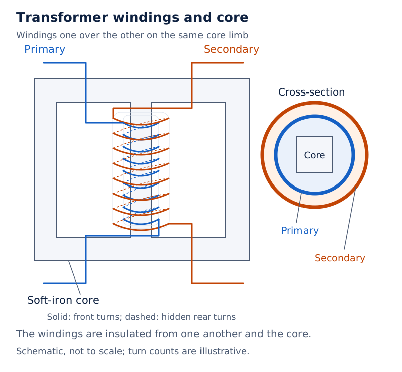
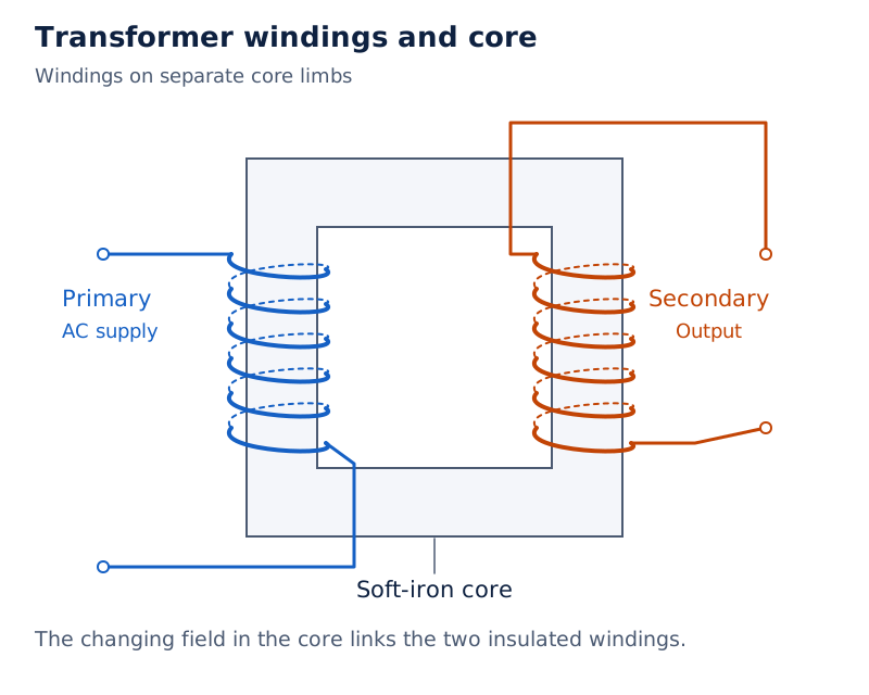
Two arrangements are shown. One has primary and secondary windings placed one over the other on a core limb. The other places the primary and secondary on separate limbs. Both drawings label a soft-iron core.
Drawn by One Young India.
Which coil has more turns?
An ideal transformer is a model with no energy losses. A load is the external circuit receiving electrical energy. For an ideal transformer supplying a load, increased voltage is accompanied by decreased current; decreased voltage is accompanied by increased current.
| Characteristic | Step-up transformer | Step-down transformer |
|---|---|---|
| Secondary turns compared with primary | More turns | Fewer turns |
| Output voltage compared with input | Higher voltage | Lower voltage |
| Output current in an ideal transformer supplying a load | Lower than the input current | Higher than the input current |
| Winding carrying the higher current | Primary winding | Secondary winding |
| Use in power transmission and distribution | Raises voltage before long-distance transmission. | Lowers voltage near consumers for distribution and use. |
High-current, low-voltage windings use thicker wire to reduce heating losses. Thus, the primary is the high-current winding in a step-up arrangement, while the secondary is the high-current winding in a step-down arrangement. Coil characteristics include both turn number and suitability for carrying current.
Actual transformers have small energy losses. The ideal comparison must not be presented as a claim that every real transformer transfers all its input energy to the output. In a labelled sketch, identify the supply side, output side and relative number of turns.
Derivation: How are transformer voltage and current ratios obtained?
Assume an ideal transformer with negligible winding resistance, no energy losses and the same changing flux linking each turn of both windings. Let be the induced voltage per turn, and and the primary and secondary turn counts.
- The common flux change produces the same voltage per turn. Adding the turn voltages gives and .
- Divide the secondary equation by the primary equation to cancel the common voltage per turn: .
- For an ideal transformer supplying a resistive load, use rms values so that input power equals output power: . Rearranging gives .
Result: and . Subscripts and identify primary and secondary. Voltages are in V, currents in A and turn counts have no unit. Use corresponding rms values or amplitudes consistently.
Worked example 6. An ideal transformer has 100 primary turns and 200 secondary turns. Its input is 220 V at 10 A. Find its output voltage and current.
Answer: The turns ratio is . Formula: and .
Substitute: , and . The output is 440 V at 5.0 A.
For a resistive load, interpreting the stated voltages and currents as rms values, check power conservation: and . The voltage doubles and the current halves, while the ideal transferred power stays the same.
Glossary
- Magnetic field — The region in which magnetic force can be detected, described by magnitude and direction.
- Magnetic field lines — Lines representing field direction, with their closeness indicating relative magnetic field strength.
- Uniform magnetic field — A magnetic field having the same magnitude and direction throughout the region considered.
- Solenoid — A cylindrical coil formed from many closely wound circular turns of insulated conducting wire.
- Electromagnet — A magnet formed when a current-carrying coil magnetises a core such as soft iron.
- Permanent magnet — A magnet that retains its magnetisation for a long period after the magnetising field is removed.
- Direct current — Electric current that flows in one direction rather than reversing its direction periodically.
- Alternating current — Electric current that reverses direction periodically as its variation repeats through complete cycles.
- Split-ring commutator — A conducting ring divided into insulated halves, used to reverse current connections to a motor coil.
- Electromagnetic induction — Production of induced voltage through changing magnetic linkage, allowing current in a closed conducting circuit.
- Galvanometer — A sensitive instrument used to detect small electric currents and indicate their direction.
- Slip rings — Complete conducting rings connecting a rotating generator coil to the external circuit through stationary brushes.
- Frequency — The number of complete cycles occurring each second, measured in the unit hertz.
- Transformer — A device using linked coils and electromagnetic induction to raise or lower an alternating voltage.
- Mutual induction — The induction of voltage in one coil due to changing current in another nearby coil.
Common errors and misconceptions
- Misconception: Field lines stop at a magnet’s south pole. Correct: They continue through the magnet from south to north, forming closed curves with the external field lines.
- Misconception: The right-hand thumb rule gives force direction. Correct: It gives the magnetic field direction around a straight current-carrying wire; Fleming’s left-hand rule gives the force direction.
- Misconception: A nearby stationary magnet maintains current in a stationary coil. Correct: Induction requires changing magnetic linkage, not merely the presence of a magnetic field.
- Misconception: A motor and generator have the same energy input. Correct: A motor receives electrical energy; a generator receives mechanical energy. Their useful energy transfers run in opposite directions.
- Misconception: The simple DC motor uses two complete slip rings. Correct: It uses a split-ring commutator. Two complete slip rings belong in the simple AC-generator arrangement.
- Misconception: Household AC at 50 Hz reverses direction fifty times per second. Correct: It completes fifty cycles and reverses direction one hundred times per second.
- Misconception: A step-up transformer has more primary than secondary turns. Correct: Its secondary has more turns, producing a higher output voltage with a lower output current in the ideal loaded arrangement.
- Misconception: Higher transformer output voltage means extra energy has been created. Correct: An ideal transformer conserves transferred power, while an actual transformer also has energy losses.
Exam-style questions with model answers
Q1. A straight copper wire is placed parallel to and above a compass needle. Current is passed through the wire and then reversed. State the two compass observations. [2 marks]
- When current flows, the needle deflects because the wire produces a magnetic field around it.
- When the current is reversed, the needle deflects in the opposite direction because the wire’s magnetic field reverses.
Q2. State the pattern of magnetic field lines around a straight current-carrying wire and explain how the right-hand thumb rule determines their direction. [3 marks]
- The magnetic field lines are concentric circles centred on the wire, lying in planes perpendicular to the direction of the straight conductor.
- Imagine gripping the conductor with the right hand, with the thumb pointing along the direction of the current through the wire.
- The curled fingers indicate the direction of the circular magnetic field lines around the conductor, and reversing current reverses that direction.
Q3. Compare a soft-iron electromagnet with a permanent magnet in terms of current supply, strength control, pole reversal and persistence of magnetisation. [4 marks]
- An electromagnet needs current in its coil to maintain the magnetising field; a permanent magnet needs no continuous current supply.
- The electromagnet’s field can be changed by changing coil current; a permanent magnet has no corresponding supply-current control during ordinary use.
- Reversing current reverses the electromagnet’s poles; a permanent magnet has no supply current whose reversal can interchange its poles.
- Soft iron loses its magnetisation when the magnetising field is removed; a permanent magnet retains magnetisation for a long period.
Q4. Describe the four main parts of a simple DC motor: coil, magnet, split-ring commutator and brushes. Also state its energy transfer. [5 marks]
- The rectangular conducting coil is placed between magnetic poles and can rotate about an axle. It carries the current supplied by the electrical circuit.
- The magnet provides the magnetic field in which the current-carrying coil experiences forces. This force effect is the principle on which the motor depends.
- The split-ring commutator consists of two insulated conducting halves connected to the coil ends. It reverses the current connection to the coil.
- The brushes are stationary conducting contacts connected to the battery. They touch the split-ring halves, providing electrical contact with the rotating coil assembly.
- The motor converts electrical energy from the supply into mechanical energy associated with the rotation of the coil and the mechanism it drives.
Q5. A closed coil is connected to a galvanometer. A bar magnet’s north pole is pushed towards it, held stationary, withdrawn, and then pushed towards it faster than before. Describe the four observations. [4 marks]
- During approach, the galvanometer deflects because the changing magnetic field linked with the coil induces a current.
- While the magnet is stationary relative to the coil, the galvanometer shows no deflection because the magnetic linkage is unchanged.
- During withdrawal of the same pole, the pointer deflects in the opposite direction, showing that the induced current has reversed.
- During the faster approach, the deflection is larger than during the original approach, showing a greater induced current.
Q6. State Fleming’s right-hand rule, naming the quantity represented by each of the three mutually perpendicular fingers. [3 marks]
- Stretch the thumb, forefinger and middle finger of the right hand so that they are mutually perpendicular; point the forefinger along the magnetic field.
- Point the thumb in the direction in which the conductor is moved across the magnetic field by the external mechanical action.
- The middle finger then indicates the direction of the induced current, provided the conductor forms part of a closed conducting circuit.
Q7. An alternating current has a frequency of 50 Hz and changes direction twice per complete cycle. How many cycles and how many direction changes occur in one second? [2 marks]
- There are 50 complete cycles in one second, because frequency in hertz gives the number of cycles per second.
- There are 2 × 50 = 100 direction changes in one second, because each cycle contains two reversals.
Q8. An ideal transformer has more turns in its secondary than its primary, receives an alternating supply and delivers energy to a load. Identify its type, compare its output voltage and current with its input, explain the induction principle, and give its transmission use. [5 marks]
- It is a step-up transformer because the secondary winding has more turns than the primary winding connected to the alternating supply.
- The secondary output voltage is higher than the primary input voltage. The greater secondary turn number distinguishes this arrangement from a step-down transformer.
- For the ideal transformer supplying a load, the output current is lower than the input current, with no energy loss in the ideal model.
- Alternating primary current produces a changing magnetic field in the core. This field links the secondary winding and induces a voltage in it.
- A step-up transformer raises voltage before long-distance transmission. For the same transmitted power, the lower current reduces heating losses in the transmission wires.
Key takeaways
- A current-carrying conductor produces a magnetic field, and reversing the current reverses the field direction around it.
- The right-hand thumb rule gives circular field direction; Fleming’s left-hand rule gives force direction for the motor effect.
- Magnetic field lines form closed curves, never intersect, and are drawn closer together where the field is stronger.
- A soft-iron electromagnet uses a current-carrying coil; changing or reversing current changes its field strength or polarity.
- Electromagnetic induction requires changing magnetic linkage, producing induced current when the conducting circuit is closed.
- A motor converts electrical energy into mechanical energy, while a generator converts mechanical energy into electrical energy.
- Household AC in India completes fifty cycles per second and changes direction twice during every complete cycle.
- A step-up transformer has more secondary turns; a step-down transformer has fewer, enabling suitable voltage changes for transmission and use.
Test yourself
Why can magnetic field lines not intersect?
An intersection would require two different magnetic field directions at the same point, which a compass needle cannot indicate.
What happens to the field when you move farther from a straight wire carrying the same current?
The magnetic field becomes weaker as distance from the wire increases, with current kept unchanged.
What do parallel, equally spaced magnetic field lines represent?
They represent a uniform magnetic field having the same magnitude and direction throughout the region shown.
What does the thumb represent in Fleming’s left-hand rule?
It represents the force or resulting motion of the current-carrying conductor in the external magnetic field.
Why does a stationary magnet fail to maintain induced current in a stationary coil?
The magnetic field linked with the coil is not changing, so the required condition for induction is absent.
Which ring arrangement belongs to a simple AC generator?
Two complete slip rings connect the rotating coil ends to stationary brushes and the external circuit.
Why is a higher transmission voltage useful for the same transmitted power?
It allows a lower current, which reduces the heating losses in wires during long-distance transmission.
Which winding has more turns in a step-down transformer, and what happens to voltage?
The primary has more turns than the secondary, and the secondary output voltage is lower than the primary input voltage.
Write about it
Turn a question from this chapter into a paper.
The Writing Studio has a structure guide, a rubric and citation tools for 15 formats, from essays to research papers. Drafting is free with an account. Learnacy Essential adds feedback from an AI writing coach and submission to The OYI Review.
Publication depends on review and is not guaranteed.