
Electricity | CBSE Class 10 Science Notes
On this page
Watch & explore
Start with a few high-quality watches, then dive into the notes below.
Try an idea before you read. Can the same two resistors make a battery supply more current? Explore Circuit Detective →

Learnacy Labs Try it hands-on: open the Electricity lab
This note covers electric current, circuits, potential difference, circuit symbols, Ohm’s law, resistance and resistivity, series and parallel combinations, the heating effect of current, fuses, electric power and electrical energy.
What is electric current, and how does a circuit carry it?
Electric current is the rate of flow of electric charge through a particular area of a conductor. A conductor provides a path for charge to flow. In metallic wires, the moving charges are electrons, which carry negative charge.
A torch bulb glows when its switch completes a conducting link between the cell and bulb. An electric circuit is a continuous, closed path for current. If the path breaks anywhere, or the switch is turned off, current stops and the bulb does not glow.
How are charge and current related?
Let Q represent the net electric charge crossing a cross-section, t the time taken, and I the electric current. A cross-section is the area across the conductor through which the charge passes.
I = Q/t
The SI unit of electric charge is coulomb, written C. SI means the International System of Units. One coulomb corresponds to the magnitude of charge contained in nearly 6 × 10¹⁸ electrons. An electron has a negative charge of magnitude 1.6 × 10⁻¹⁹ C.
The SI unit of electric current is ampere, written A, named after the French scientist Andre-Marie Ampere, who lived from 1775 to 1836. One ampere means one coulomb of charge passing per second, where s denotes second.
1 A = 1 C/1 s. Smaller currents use milliampere, mA, or microampere, µA: 1 mA = 10⁻³ A and 1 µA = 10⁻⁶ A.
Which direction does current take?
Conventional current follows the direction assigned to positive charge flow. In a metallic circuit, this is opposite to electron flow. Through the external circuit, current travels from the cell’s positive terminal towards its negative terminal.
An ammeter measures current. It is always connected in series, meaning in the same path as the component whose current is measured.
What the figure shows
A simple electric circuit
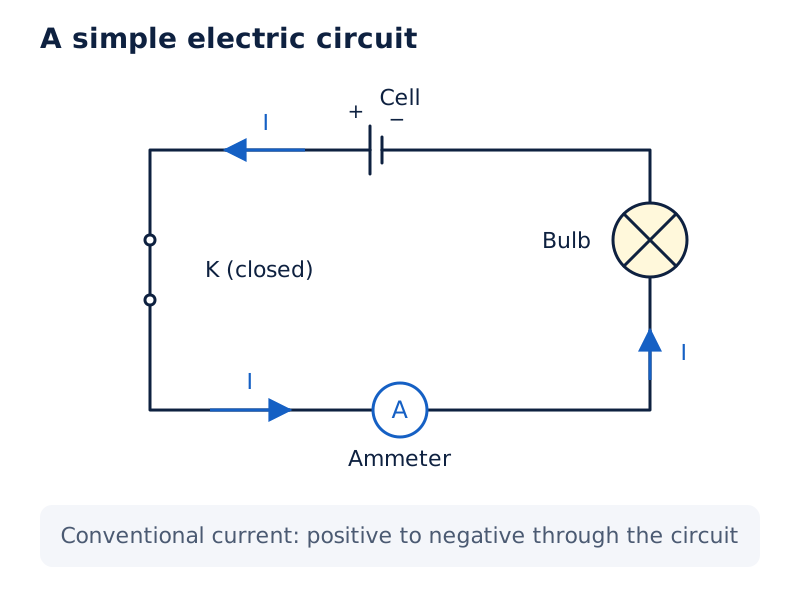
The loop contains a cell, bulb, ammeter and plug key labelled K. Arrows marked I show current passing through the bulb and ammeter and returning towards the cell’s negative terminal.
Drawn by One Young India. See Fig. 11.1 in your NCERT textbook
Worked example 11.1. A bulb filament draws 0.5 A for 10 minutes. Find the charge flowing through the circuit.
Formula: Q = It. Substitute: t = 10 × 60 = 600 s; Q = 0.5 × 600.
Answer: 300 C of charge flows through the circuit.
What is potential difference, and how are circuits represented?
Charges do not flow through a copper wire by themselves. A difference in electric pressure, called potential difference, sets electrons in motion along the conductor. A cell produces this difference through chemical action, even when no current is drawn from it.
A battery, consisting of one or more cells, can maintain potential difference. To keep current flowing in a connected conducting circuit, the source expends its stored chemical energy. The terminals are the connection points at the ends of the cell.
How is potential difference measured?
Definition: Potential difference between two points in a current-carrying circuit is the work done to move a unit charge from one point to the other.
Let V represent potential difference and W the work done, meaning energy transferred in moving charge Q between the points. Then:
V = W/Q
The SI unit of potential difference is volt, also written V. It is named after the Italian physicist Alessandro Volta, who lived from 1745 to 1827. The unit of work is joule, written J.
1 V = 1 J/1 C. Thus, a potential difference of one volt means one joule of work per coulomb of charge moved.
A voltmeter measures potential difference. It is always connected in parallel across the two measurement points, meaning on a separate branch joining those points. An ammeter measures current through a path; a voltmeter compares the two ends of a component.
Worked example 11.2. How much work is done in moving 2 C of charge between points with a potential difference of 12 V?
Formula: W = VQ. Substitute: W = 12 × 2.
Answer: The work done is 24 J.
What do conventional circuit symbols show?
A schematic diagram uses agreed symbols to show the components and connections of a circuit. It can include a cell or battery, connecting wires, a plug key and electrical components. The distinction between connected wires and wires that merely cross matters when tracing the current path.
| Component or connection | Symbol to recognise |
|---|---|
| Electric cell | One long and one short parallel line, with positive and negative terminal markings |
| Battery | Repeated pairs of long and short parallel lines |
| Open or closed plug key | An unfilled gap or a filled contact between the key terminals |
| Wire joint | A dot at the meeting of connecting lines |
| Wires crossing without joining | A curved bridge at the crossing |
| Ammeter and voltmeter | A circle containing A or V respectively |
How does Ohm’s law connect current, voltage and resistance?
Voltage is another name for potential difference. In 1827, German physicist Georg Simon Ohm, who lived from 1787 to 1854, established the relationship between voltage across a metallic wire and the current through it.
Definition: Ohm’s law states that the potential difference across a given metallic wire is directly proportional to the current through it, provided its temperature remains the same.
Here, directly proportional means that the ratio V/I remains constant. This constant is the wire’s resistance, represented by R: the property that resists the flow of charges through a conductor.
V = IR
R = V/I
I = V/R
The SI unit of resistance is ohm, written Ω. A conductor has resistance one ohm when one volt across it produces one ampere through it: 1 ohm = 1 V/1 A.
How can the relationship be investigated?
Nichrome is an alloy, a material combining nickel, chromium, manganese and iron. A nichrome wire of length about 0.5 m can be used to study how current changes with applied voltage. Here m is the unit metre.
- Connect the nichrome wire, an ammeter, a plug key and cells in a circuit; connect a voltmeter across the wire.
- Use one 1.5 V cell and record the current and potential difference.
- Repeat separately with two, three and four such cells, recording each pair of readings.
- Calculate V/I for every pair and plot potential difference against current.
The ratios are approximately the same. The graph is a straight line through the origin, the point where both plotted quantities are zero.
What the figure shows
Testing Ohm’s law
The wire runs between points X and Y. An ammeter and key are in its circuit path, while the voltmeter connects across X and Y. The cells are shown along the upper part of the circuit.
See Fig. 11.2 in your NCERT textbook
What the figure shows
Potential difference against current
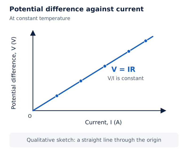
Current in amperes is on the horizontal axis and potential difference in volts on the vertical axis. The plotted points lie along a rising straight line through the origin.
Drawn by One Young India. See Fig. 11.3 in your NCERT textbook
How can resistance control current?
At a fixed potential difference, current is inversely proportional to resistance: doubling resistance halves current. A variable resistance regulates current without changing the voltage source. A rheostat is a device often used to change resistance in a circuit.
Worked example 11.3. Find the currents drawn from a 220 V source by a bulb filament of resistance 1200 Ω and a heater coil of resistance 100 Ω.
Formula: I = V/R. Substitute: for the bulb, I = 220/1200; for the heater, I = 220/100.
Answer: The bulb draws about 0.18 A; the heater draws 2.2 A.
Worked example 11.4. A heater draws 4 A at 60 V. Find its current at 120 V using the same resistance.
Formula: R = V/I; I = V/R. Substitute: R = 60/4 = 15 Ω; the new current is 120/15.
Answer: The heater draws 8 A.
Which factors determine the resistance of a wire?
Electrons in a conductor are not completely free to move. Attraction by the atoms among which they move restrains them. A component of a given size with low resistance is a good conductor; one with appreciable resistance is called a resistor.
A component of identical size with higher resistance is a poor conductor. An insulator offers even higher resistance for the same size. Comparing sizes matters because resistance depends on both the material and the dimensions of the component.
How do length and thickness affect resistance?
Let l be the length of a uniform metallic wire, and A its cross-sectional area. Here A represents an area, while A following a current value means ampere. Resistance is directly proportional to length and inversely proportional to cross-sectional area.
R = ρl/A
The Greek letter ρ, read as rho, represents electrical resistivity, the proportionality constant characteristic of the material. The SI unit of resistivity is ohm metre, written Ω m. Both resistance and resistivity vary with temperature.
- Connect a cell, ammeter, plug key and nichrome wire of length l; measure the current.
- Replace it with nichrome wire of the same thickness but twice the length. The ammeter reading decreases to one-half.
- Use a thicker nichrome wire of the original length. The larger cross-sectional area produces an increased ammeter reading.
- Use copper wire with the original length and cross-sectional area. A change in current shows that the material also matters.
Note: In comparisons of length or area, keep the material and other relevant conditions the same. A change of temperature can change the resistance, so it must not be silently treated as unchanged.
How are dimensions used in calculations?
For a circular wire, let d mean diameter, the distance across the circular cross-section through its centre. Its area is A = πd²/4, where π is the circle constant. Convert millimetres, written mm, to metres before calculating resistivity in Ω m.
Worked example 11.5. A metal wire is 1 m long, has diameter 0.3 mm and resistance 26 Ω at 20°C. Find its resistivity and identify the metal using the value for manganese, 1.84 × 10⁻⁶ Ω m at 20°C. The symbol °C means degrees Celsius.
Formula: A = πd²/4; ρ = RA/l. Substitute: d = 3 × 10⁻⁴ m; ρ = 26 × π × (3 × 10⁻⁴)²/(4 × 1).
Answer: The resistivity is approximately 1.84 × 10⁻⁶ Ω m, matching manganese.
Worked example 11.6. A wire of length l and area A has resistance 4 Ω. Find the resistance of another wire of the same material with length l/2 and area 2A, taking the resistivity as unchanged.
Formula: R₁ = ρl/A; R₂ = ρ(l/2)/(2A). Here R₁ and R₂ are the first and second wire’s resistances. Substitute: R₂ = R₁/4 = 4/4.
Answer: The second wire has resistance 1 Ω.
How does resistivity explain the choice of electrical materials?
Resistance describes a particular conductor, including the effects of its dimensions. Resistivity is characteristic of its material at a given temperature. This distinction explains why wires of the same material can have different resistances when their lengths or thicknesses differ.
Metals and alloys have very low resistivity and are good conductors of electricity. Insulating materials such as rubber and glass have much higher resistivity. A material’s resistivity must be compared at a stated temperature because it changes with temperature.
Which materials have low resistivity?
The following values refer to 20°C. They illustrate differences between conducting materials and provide data for numerical comparisons.
| Material | Resistivity at 20°C in Ω m |
|---|---|
| Silver | 1.60 × 10⁻⁸ |
| Copper | 1.62 × 10⁻⁸ |
| Aluminium | 2.63 × 10⁻⁸ |
| Tungsten | 5.20 × 10⁻⁸ |
| Iron | 10.0 × 10⁻⁸ |
| Manganese | 1.84 × 10⁻⁶ |
Of these materials, silver has the lowest resistivity. Copper and aluminium are generally used for electrical transmission lines, the wires carrying electrical energy. The choice of material changes resistance even when the wire’s length and area are unchanged.
Why are alloys useful for heating devices?
An alloy’s resistivity is generally higher than that of its constituent metals. Alloys do not oxidise, or burn, readily at high temperatures. They are therefore commonly used in electrical heating devices such as electric irons and toasters.
Tungsten is used almost exclusively for the filaments of electric bulbs. A filament is the wire in a bulb that becomes hot and emits light. Its ability to remain solid at high temperature is important alongside its electrical properties.
How are resistors combined in series?
Resistors are in series when joined end to end in the same current path. The current is the same through every resistor. Moving an ammeter to different positions in that path gives the same reading.
The total potential difference across the combination equals the sum of the potential differences across its individual resistors. These separate potential differences can be measured by connecting a voltmeter across each resistor in turn.
An equivalent resistance is the resistance of a single replacement resistor that gives the same current under the same applied potential difference. Let Rₛ denote the equivalent resistance of the series combination.
What the figure shows
Resistors in series
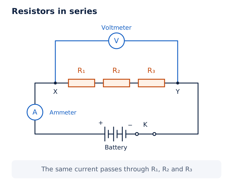
Three resistors labelled R₁, R₂ and R₃ lie end to end between X and Y. The voltmeter spans X and Y, while the ammeter, battery and key share the main circuit path.
Drawn by One Young India. See Fig. 11.6 in your NCERT textbook
Derivation: Equivalent resistance in series
Let R₁, R₂ and R₃ be the individual resistances, and V₁, V₂ and V₃ the potential differences across them. Let V be the total potential difference and I the common current.
- Add the individual potential differences: V = V₁ + V₂ + V₃.
- Apply Ohm’s law separately: V₁ = IR₁, V₂ = IR₂ and V₃ = IR₃.
- For the equivalent resistor, V = IRₛ. Substitution gives IRₛ = IR₁ + IR₂ + IR₃.
- Cancel the common non-zero current I to obtain the sum of the individual resistances.
Rₛ = R₁ + R₂ + R₃
The series resistance is greater than any individual resistance.
How are current and individual voltages calculated?
Worked example 11.7. A lamp of resistance 20 Ω and a conductor of resistance 4 Ω are connected in series to a 6 V battery. Find the total resistance, current and potential difference across each component.
Formula: Rₛ = R₁ + R₂; I = V/Rₛ; V₁ = IR₁; V₂ = IR₂. Here the subscripts 1 and 2 refer to the lamp and conductor.
Substitute: Rₛ = 20 + 4 = 24 Ω; I = 6/24 = 0.25 A. The lamp voltage is 0.25 × 20 = 5 V; the conductor voltage is 0.25 × 4 = 1 V.
Answer: 24 Ω, 0.25 A, 5 V and 1 V, respectively. The two voltages add to the battery’s 6 V. A single 24 Ω resistor would also draw 0.25 A from this battery.
How are resistors combined in parallel?
Resistors are in parallel when connected between the same two points, creating separate current paths called branches. The potential difference across each resistor equals the potential difference across the whole combination.
The total current divides among the branches. To measure a branch current, connect the ammeter in series with that branch’s resistor. The current entering the combination equals the sum of the currents through all its branches.
Derivation: Equivalent resistance in parallel
Let Rₚ be the equivalent parallel resistance. Let I₁, I₂ and I₃ denote the branch currents through resistances R₁, R₂ and R₃. The common potential difference is V, and I is the total current.
- Add the branch currents: I = I₁ + I₂ + I₃.
- Apply Ohm’s law to the equivalent resistor: I = V/Rₚ.
- Apply Ohm’s law to each branch: I₁ = V/R₁, I₂ = V/R₂ and I₃ = V/R₃.
- Substitute to give V/Rₚ = V/R₁ + V/R₂ + V/R₃. Divide by the common non-zero potential difference V.
1/Rₚ = 1/R₁ + 1/R₂ + 1/R₃
The reciprocal of a quantity means one divided by that quantity. Add the reciprocals of the individual resistances, then take the reciprocal of the sum to find the equivalent resistance.
How are branch currents and total current found?
Worked example 11.8. Resistors of 5 Ω, 10 Ω and 30 Ω are connected in parallel across a 12 V battery. Calculate each branch current, the total current and the total resistance.
Formula: I₁ = V/R₁; I₂ = V/R₂; I₃ = V/R₃; I = I₁ + I₂ + I₃. The subscripts follow the three resistances in the order given.
Substitute: I₁ = 12/5 = 2.4 A; I₂ = 12/10 = 1.2 A; I₃ = 12/30 = 0.4 A. Thus I = 2.4 + 1.2 + 0.4 = 4 A.
Answer: The branch currents are 2.4 A, 1.2 A and 0.4 A; total current is 4 A. Since 1/Rₚ = 1/5 + 1/10 + 1/30 = 1/3 in reciprocal ohms, the equivalent resistance is 3 Ω.
All branches receive the same 12 V in this example. Their currents differ because their resistances differ. The branch with the smaller resistance carries the larger current, consistent with I = V/R at fixed voltage.
How do mixed combinations work, and why is parallel connection useful?
A circuit can contain both series and parallel groups. Identify which resistors share two connection points, replace each parallel group by its equivalent resistance, and then combine groups that lie in series.
How is a mixed circuit simplified?
Worked example 11.9. A 10 Ω resistor and a 40 Ω resistor form one parallel group. A 30 Ω, a 20 Ω and a 60 Ω resistor form a second parallel group. The groups are in series across 12 V. Find total resistance and current.
Formula: R = R′ + R″; I = V/R. Here R′ and R″ mean the equivalent resistances of the first and second groups, and R is their total series resistance.
Substitute: 1/R′ = 1/10 + 1/40 = 5/40, so R′ = 8 Ω. Also, 1/R″ = 1/30 + 1/20 + 1/60 = 6/60, so R″ = 10 Ω.
Answer: Total resistance R = 8 + 10 = 18 Ω. The current is I = 12/18, approximately 0.67 A.
What the figure shows
A mixed resistor circuit
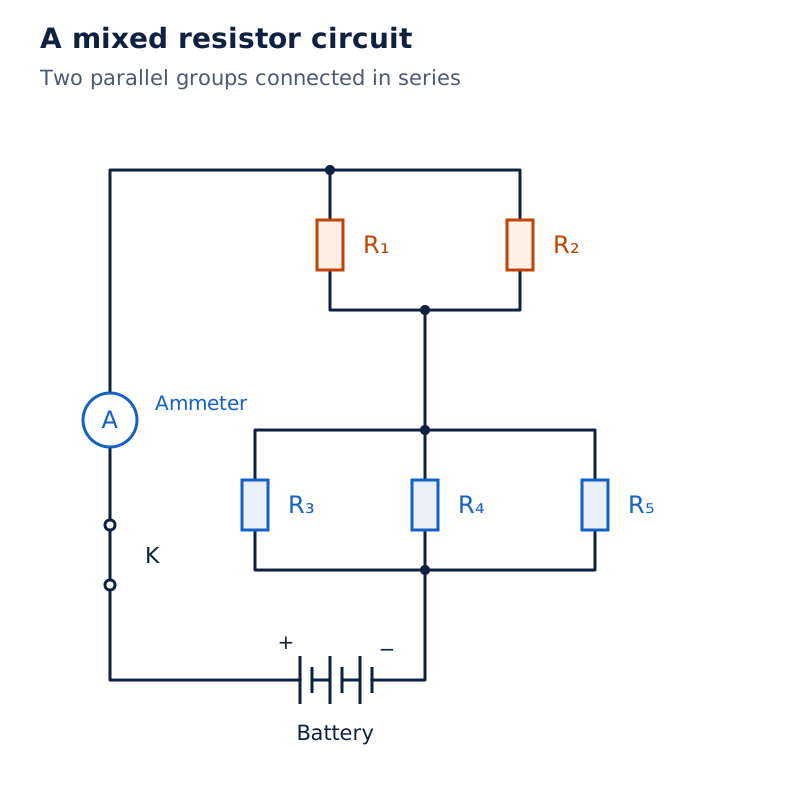
The upper group has two parallel resistors labelled R₁ and R₂. The lower group has three labelled R₃, R₄ and R₅. These groups share a series loop containing a battery, ammeter and key.
Drawn by One Young India. See Fig. 11.12 in your NCERT textbook
How do series and parallel connections differ?
| Feature | Series connection | Parallel connection |
|---|---|---|
| Current | The same current passes through each resistor | The total current divides among separate branches |
| Potential difference | Individual potential differences add to the total | The same potential difference acts across every branch |
| Equivalent resistance | Add the individual resistances | Add reciprocals, then take the reciprocal of their sum |
| Different appliance requirements | A common current is unsuitable for appliances needing widely different currents | Different branch resistances can draw different currents |
Connecting an electric bulb and heater in series is impracticable because they need widely different currents to operate properly. Another major disadvantage is that if one component fails and breaks the series circuit, none of the components works.
A parallel circuit divides current between appliances and decreases total resistance. This is particularly helpful when appliances have different resistances and need different currents. A failed bulb in a series string of decorative lights can require checking each bulb to locate the break.
Why does an electric current produce heat?
A cell continually supplies energy to maintain current. Part of that energy may perform useful work, such as turning fan blades; the rest may raise the appliance’s temperature. A fan can therefore become warm when used continuously for a long time.
In a purely resistive circuit, consisting of resistors connected to a battery, the supplied energy is dissipated entirely as heat. Dissipation here means conversion of supplied electrical energy into heat. This is the heating effect of electric current.
Derivation: Joule’s law of heating
Let H denote heat produced, and P the power input, meaning energy supplied per unit time. Consider steady current I through resistance R for time t, with potential difference V across it and charge Q passing through it.
- The work done to move charge Q through potential difference V is W = VQ.
- Since Q = It, the supplied energy becomes W = VIt; the power is P = W/t = VI.
- In the resistor this energy becomes heat, giving H = VIt.
- Substitute V = IR from Ohm’s law to obtain H = I × R × I × t.
H = I²Rt
This is Joule’s law of heating. For a given resistance and duration, heat is directly proportional to the square of current. For a given current and duration, it is proportional to resistance. For a given current and resistance, it is proportional to time.
H = VIt
Use current in amperes, resistance in ohms and time in seconds to obtain heat in joules. When the supply voltage and resistance are known, calculate current using I = V/R before substituting into the heating formula.
How are heating calculations carried out?
The SI unit of power is watt, written W: 1 W = 1 J/s. Here W after a numerical value means watt; W used as a quantity in W = VQ means work done.
Worked example 11.10. An electric iron consumes 840 W at maximum heating and 360 W at minimum heating, on a 220 V supply. Find its current and resistance in each case.
Formula: I = P/V; R = V/I. Substitute: maximum current is 840/220 ≈ 3.82 A; minimum current is 360/220 ≈ 1.64 A.
Answer: At maximum heating, I ≈ 3.82 A and, using this rounded current, R = 220/3.82 ≈ 57.59 Ω. At minimum heating, I ≈ 1.64 A and, using this rounded current, R = 220/1.64 ≈ 134.15 Ω.
Worked example 11.11. A 4 Ω resistor produces 100 J of heat each second. Find the potential difference across it.
Formula: I = √(H/Rt); V = IR. The sign √ means square root. Substitute: I = √[100/(4 × 1)] = 5 A; V = 5 × 4.
Answer: The potential difference is 20 V.
How is the heating effect used in appliances and fuses?
Heating in a conductor can be undesirable because it converts useful electrical energy into heat and can change component properties. It also has useful applications in an electric laundry iron, toaster, oven, kettle and heater.
How does a bulb filament produce light?
A bulb filament must retain as much generated heat as possible so that it becomes very hot and emits light. It must also remain solid. Tungsten, a strong metal with melting point 3380°C, is used for bulb filaments.
The filament should be thermally isolated as much as possible, meaning that heat transfer away from it is reduced, using insulating supports. Bulbs are usually filled with chemically inactive nitrogen and argon gases to prolong filament life.
Most of the power consumed by the filament appears as heat; a small part is radiated as light.
How does a fuse protect a circuit?
A fuse is a wire of metal or alloy with an appropriate melting point, placed in series with a device. Examples of fuse-wire materials include aluminium, copper, iron and lead. It stops current when an unduly high current flows.
- A current larger than the specified value flows through the series-connected fuse.
- The heating effect raises the temperature of its wire.
- The fuse wire melts and breaks the conducting path.
- The circuit opens, stopping current through the protected device.
A fuse wire is usually encased in a porcelain cartridge, or a similar material, with metal ends. Domestic fuse ratings include 1 A, 2 A, 3 A, 5 A and 10 A. A rating specifies the current value associated with the fuse’s use.
For an iron consuming 1 kilowatt, written kW and equal to 1000 W, at 220 V, the current is 1000/220 ≈ 4.55 A to two decimal places. In this case, a 5 A fuse must be used.
How are electric power, energy and operating cost calculated?
Electric power is the rate at which electrical energy is consumed or dissipated. It is distinct from energy: power describes the rate of use, while energy depends on both the rate and the duration of operation.
P = VI
Using Ohm’s law for a resistor gives two further expressions:
P = I²R
P = V²/R
One watt is the power consumed when a device carries one ampere at one volt: 1 W = 1 V × 1 A. A kilowatt is 1000 watts.
How does power give electrical energy?
Let E denote the electrical energy consumed. Then E = Pt, with P as power and t as operating time. This is the same energy relation used when supplied energy is written as W = VIt.
A watt hour, written Wh, is the energy consumed by one watt operating for one hour. A kilowatt hour, written kWh, is the commercial unit of electrical energy, commonly called one unit.
1 kWh = 1000 W × 3600 s = 3.6 × 10⁶ J. Use kilowatts and hours together to obtain energy in kilowatt hours. Use watts and seconds together to obtain energy in joules.
Note: Electrons are not consumed in an electric circuit. Payment for electricity is payment for the energy used to move electrons through appliances, not for a supply of electrons that disappears during use.
How are power and cost found in practice?
Worked example 11.12. An electric bulb is connected to a 220 V generator and carries 0.50 A. Find its power. A generator here supplies electrical energy to the circuit.
Formula: P = VI. Substitute: P = 220 × 0.50 = 110 J/s.
Answer: The power of the bulb is 110 W.
Worked example 11.13. A refrigerator rated 400 W operates for 8 hours daily. Find its operating cost for 30 days at Rs 3.00 per kWh, where Rs denotes rupees.
Formula: E = Pt; cost = energy in kWh × price per kWh. Substitute: E = 400 × 8 × 30 = 96000 Wh = 96 kWh.
Answer: Cost = 96 × Rs 3.00 = Rs 288.00 for the 30 days.
Glossary
- Electric current — Rate at which electric charge flows through a particular area of a conductor.
- Electric circuit — A continuous and closed conducting path through which electric current can flow.
- Ampere — Unit of current corresponding to one coulomb of charge flowing per second.
- Potential difference — Work done per unit charge moved between two points in a current-carrying circuit.
- Voltmeter — Instrument connected in parallel across two points to measure their potential difference.
- Resistance — Property of a conductor that resists the flow of electric charges through it.
- Ohm — Resistance allowing one ampere of current when one volt is applied across a conductor.
- Resistivity — Characteristic property of a material relating resistance to a conductor’s length and cross-sectional area.
- Rheostat — Device often used to change circuit resistance and thereby regulate electric current.
- Series combination — Arrangement of resistors joined end to end with the same current passing through each.
- Parallel combination — Arrangement of resistors between the same two points, giving each the same potential difference.
- Heating effect — Conversion of supplied electrical energy into heat when current passes through a resistor.
- Fuse — Series-connected wire that melts and breaks a circuit when current exceeds its specified value.
- Electric power — Rate at which electrical energy is dissipated or consumed in an electric circuit.
- Kilowatt hour — Commercial unit of electrical energy equal to the energy used by one kilowatt in one hour.
Common errors and misconceptions
- Misconception: Conventional current follows electron flow in a metallic wire. Correct: Conventional current is assigned the opposite direction to the flow of negatively charged electrons.
- Misconception: Ammeters and voltmeters are connected in the same way. Correct: An ammeter is connected in series with the measured path; a voltmeter is connected in parallel across the measurement points.
- Misconception: Ohm’s law applies without a temperature condition. Correct: The direct proportionality between voltage and current requires the metallic wire’s temperature to remain the same.
- Misconception: Resistance and resistivity are interchangeable. Correct: Resistance also depends on length and cross-sectional area; resistivity characterises the material. Both vary with temperature.
- Misconception: Parallel resistances are added directly. Correct: Add their reciprocals and take the reciprocal of that sum. Direct addition gives the resistance of a series combination.
- Misconception: A kilowatt hour measures power. Correct: It measures electrical energy. Kilowatt measures power, while kilowatt hour combines power with time.
- Misconception: A bulb converts all its electrical power into light. Correct: Most filament power appears as heat, with only a small part radiated as light.
- Misconception: Appliances consume electrons. Correct: Appliances consume electrical energy; electrons are not consumed. Electricity charges pay for the energy used.
Exam-style questions with model answers
Q1. Define electric current and state its SI unit, including the meaning of one unit. [2 marks]
- Electric current is the rate of flow of electric charge through a particular area of a conductor.
- Its SI unit is ampere. One ampere is a flow of one coulomb of charge per second: 1 A = 1 C/s.
Q2. State Ohm’s law with its condition, describe the voltage-current graph and explain how the experiment gives resistance. [3 marks]
- For a given metallic wire, potential difference is directly proportional to current, provided the temperature remains the same. In symbols, V = IR, where R is resistance.
- Plotting potential difference on the vertical axis against current on the horizontal axis gives a straight line through the origin.
- Divide each measured potential difference by its corresponding current. The approximately constant ratio V/I gives the resistance of the wire in ohms.
Q3. A wire has resistance 4 Ω, length l and cross-sectional area A. Another wire of the same material at the same temperature has length l/2 and area 2A. Find its resistance and explain the changes. [3 marks]
- Use R = ρl/A, where ρ is resistivity. The material and temperature are the same, so the resistivity is unchanged for the second wire.
- Halving the length halves the resistance if area is unchanged. Doubling the cross-sectional area then halves that resistance again, making the combined factor one-quarter.
- The new resistance is therefore 4 Ω divided by 4, giving 1 Ω. Both dimensional changes reduce the resistance.
Q4. A 20 Ω lamp and a 4 Ω conductor are connected in series across a 6 V battery. Find total resistance, current and the voltage across each component, and check the voltage sum. [5 marks]
- In series, add the individual resistances. The total resistance is 20 Ω + 4 Ω = 24 Ω for the complete combination.
- Apply Ohm’s law to the whole circuit: current = 6 V/24 Ω = 0.25 A. This same current passes through both components.
- The potential difference across the lamp is current multiplied by its resistance: 0.25 A × 20 Ω = 5 V.
- The potential difference across the conductor is calculated using its own resistance and the same current: 0.25 A × 4 Ω = 1 V.
- The separate potential differences add to 5 V + 1 V = 6 V, matching the battery voltage and checking the series relationship.
Q5. Resistors of 5 Ω, 10 Ω and 30 Ω are connected in parallel across a 12 V battery. Calculate the three branch currents, total current and equivalent resistance. [5 marks]
- Each parallel branch has the full 12 V across it. The current through the 5 Ω resistor is therefore 12/5 = 2.4 A.
- The 10 Ω resistor also receives 12 V. Its branch current is 12/10 = 1.2 A, using current equal to voltage divided by resistance.
- The 30 Ω resistor has branch current 12/30 = 0.4 A. Its higher resistance gives a smaller current at the same potential difference.
- Add the three branch currents to obtain the current drawn from the battery: 2.4 A + 1.2 A + 0.4 A = 4 A.
- The equivalent resistance is total voltage divided by total current: 12 V/4 A = 3 Ω, also obtainable by the reciprocal-resistance rule.
Q6. A 4 Ω resistor produces 100 J of heat in 1 s under a steady current. Calculate its current and the potential difference across it using Joule’s law. [3 marks]
- Joule’s law is H = I²Rt, where H is heat, I current, R resistance and t time. Substitute H = 100 J, R = 4 Ω and t = 1 s.
- Rearrange to obtain I² = H/(Rt) = 100/(4 × 1) = 25 in squared amperes. Taking the square root gives current I = 5 A.
- Apply Ohm’s law to find the potential difference: V = IR = 5 A × 4 Ω = 20 V across the resistor.
Q7. A 400 W refrigerator operates for 8 hours per day for 30 days. Electricity costs Rs 3.00 per kWh. Calculate its energy consumption and operating cost. [3 marks]
- Multiply power by total operating time. The energy used is 400 W × 8 hours per day × 30 days = 96000 Wh.
- Convert watt hours to kilowatt hours by dividing by 1000. The refrigerator therefore uses 96 kWh of electrical energy over the stated period.
- Multiply the energy by the given price per unit: 96 kWh × Rs 3.00 per kWh = Rs 288.00 for the 30 days.
Q8. Explain how a fuse is connected and how it stops an unduly high current. [2 marks]
- The fuse wire is connected in series with the device, so current through the device also passes through the fuse.
- Current above the specified value heats and melts the fuse wire, breaking the circuit and stopping current through the device.
Key takeaways
- Electric current measures charge flowing per unit time; conventional current runs opposite to electron flow in metallic wires.
- Potential difference is work done per unit charge, and a cell maintains it by expending stored chemical energy.
- Ohm’s law links voltage and current through resistance, provided the temperature of the metallic wire remains the same.
- A uniform wire’s resistance increases with length and decreases with cross-sectional area; its material is represented by resistivity.
- Series resistors carry the same current, and their individual resistances add to give the equivalent resistance.
- Parallel resistors have the same potential difference, while their branch currents add to form the total current.
- Joule’s heating law gives H = I²Rt; useful applications include heaters, bulb filaments and series-connected protective fuses.
- Power is the rate of energy consumption; multiply power by operating time to calculate energy and then its cost.
Test yourself
What makes a torch bulb stop glowing when its switch is opened?
The switch breaks the continuous conducting path, so current stops flowing through the bulb.
What does a potential difference of 1 V between two points mean?
One joule of work is done to move one coulomb of charge between those points.
How is an ammeter connected, and how is a voltmeter connected?
An ammeter is connected in series with the measured current path. A voltmeter is connected in parallel across the two measurement points.
At fixed voltage, what happens to current if resistance doubles?
The current becomes half its original value because current equals voltage divided by resistance.
Why are alloys commonly used in electric heating devices?
Their resistivity is generally higher than that of their constituent metals, and they do not oxidise readily at high temperatures.
Why is tungsten suitable for a bulb filament?
Tungsten is a strong metal with a high melting point of 3380°C, allowing the filament to become very hot and emit light.
What is one kilowatt hour in joules?
One kilowatt hour equals 3.6 × 10⁶ J, the energy consumed by one kilowatt operating for one hour.
Are electrons consumed when an appliance uses electricity?
No. Electrical energy is consumed in the appliance; electrons are not consumed in the circuit.
Circuit detective
Same resistors. A different result?
Keep a 6 V source and the same 3 Ω and 6 Ω resistors. Change their connections and look for what stays the same.
Now change the connection while the switch is open. Does current stop everywhere?
- Equivalent resistance
- 9 Ω
- Current from source
- 2/3 A
- 3 Ω resistor
- 2/3 A2 V across it
- 6 Ω resistor
- 2/3 A4 V across it
One path means the same current through both resistors. Their resistances add: 3 + 6 = 9 Ω. The source supplies 6/9 = 2/3 A, and its 6 V divides into 2 V and 4 V.
Our model: the source holds exactly 6 V; wires and a closed switch have zero resistance. The resistors stay at 3 Ω and 6 Ω at constant temperature. Readings show steady conditions, after any switching effects.
Compare all four outcomes
The switch is always beside the 3 Ω resistor. “Across” means potential difference between the two ends of the named component.
| Reading | Switch closed | Switch open |
|---|---|---|
| Equivalent resistance | 9 Ω | Open circuit |
| Source current | 2/3 A | 0 A |
| 3 Ω current | 2/3 A | 0 A |
| Across 3 Ω | 2 V | 0 V |
| 6 Ω current | 2/3 A | 0 A |
| Across 6 Ω | 4 V | 0 V |
| Across switch | 0 V | 6 V |
| Reading | Switch closed | Switch open |
|---|---|---|
| Equivalent resistance | 2 Ω | 6 Ω |
| Source current | 3 A | 1 A |
| 3 Ω current | 2 A | 0 A |
| Across 3 Ω | 6 V | 0 V |
| 6 Ω current | 1 A | 1 A |
| Across 6 Ω | 6 V | 6 V |
| Across switch | 0 V | 6 V |
Follow the gap. Opening the series circuit breaks its only path. Opening the 3 Ω path in parallel leaves a complete path through 6 Ω. That resistor still has 6 V across it and carries 1 A.
A voltage surprise: a resistor carrying no current has zero voltage across it in this model. The full 6 V is across the open switch, not across the disconnected resistor. “Open circuit” means no complete conducting path, not zero resistance.
Make a prediction of your own. Close the switch in parallel. If you could add another conducting branch, would the source supply more or less current? Explain your idea using paths, then using resistance.
Check that idea
With this ideal source holding 6 V, adding another finite, positive resistance in parallel adds branch current. Total current increases and equivalent resistance decreases. Each existing branch still has 6 V across it, so its current stays the same.