
Alternating Current | CBSE Class 12 Physics Notes
On this page
Watch & explore
Start with a few high-quality watches, then dive into the notes below.
This note covers sinusoidal alternating current, peak and rms values, phasors, resistive, inductive and capacitive circuits, series LCR circuits, resonance, average power, power factor, transformers, energy losses and electrical power transmission.
What is alternating current, and how does a resistor respond to it?
Alternating current changes direction periodically. For a sinusoidal source, the applied potential difference varies as a sine function of time. Direct current, by contrast, does not change direction with time. Alternating voltages can be changed efficiently using transformers, which helps economical transmission of electrical energy.
How are instantaneous and peak values distinguished?
Let denote instantaneous voltage, its amplitude or peak value, time and angular frequency. If is frequency and is the time period, the sinusoidal source is described by:
The SI unit of voltage is the volt, written . The SI unit of frequency is the hertz, written . Angular frequency is expressed in radians per second, , and time in seconds, . The constant is the ratio of a circle's circumference to its diameter. Frequency and angular frequency must not be confused.
Let be resistance, instantaneous current and current amplitude. The SI unit of current is the ampere, written . The SI unit of resistance is the ohm, written .
Derivation: current through a pure resistor
- Apply Kirchhoff's loop rule to the source and resistor:
- Substitute the applied voltage and divide by resistance:
- For a fixed resistance, define the current amplitude:
- Write the current in sinusoidal form:
Result: Voltage and current in a pure resistor are in phase. Their maxima, minima and zero values occur at the same respective instants. Ohm's law applies to the resistor for both alternating and direct voltages, provided its resistance remains constant.
What the figure shows
Resistor connected to an AC source
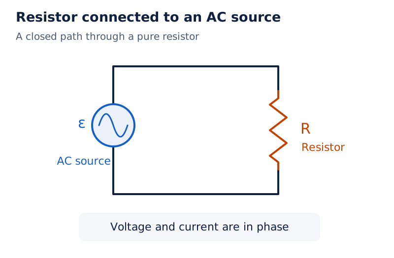
A single closed loop contains a circular alternating-source symbol on the left and a zigzag resistor on the right. The resistor is labelled ; the source is labelled , representing its emf.
Drawn by One Young India. See Fig. 7.1 in your NCERT textbook
The signed current averages to zero over a complete cycle because its positive and negative contributions cancel. This does not eliminate heating. Heating depends on the square of current, so reversing current direction does not reverse the energy dissipated in the resistor.
Why are rms values used for alternating voltage and current?
Definition: The root mean square current is the direct current that would produce the same average heating in the same resistor as the alternating current. It is also called the effective current.
Write rms current as , rms voltage as , instantaneous power as and average power as . Angle brackets denote an average over one complete cycle. The SI unit of power is the watt, written .
Derivation: rms current and average resistive power
- Express instantaneous Joule heating using the sinusoidal current:
- Use the trigonometric identity and the zero cycle-average of the cosine:
- Average the squared current over a complete cycle:
- Take the positive square root to obtain the effective current:
- Substitute in the power expression:
Result: For a sinusoid, the rms value is approximately times its peak value. Similarly, . Across a pure resistor, , so average power can also be written .
An AC voltage or current specified without further qualification ordinarily means its rms value. A power rating refers to average power. The peak voltage is larger than the stated rms voltage, and the zero average of the signed voltage is a different quantity altogether.
| Quantity | Meaning | Sinusoidal relationship |
|---|---|---|
| Instantaneous current | Current at a particular time | for the resistor |
| Peak current | Maximum current magnitude | |
| Rms current | Equivalent direct current for heating | |
| Average resistive power | Mean energy dissipation rate |
Worked example 1. A light bulb is rated at for a rms supply. Find its resistance, the peak supply voltage and its rms current.
Formula: , , .
Substitute:
- Resistance:
- Peak voltage:
- Rms current:
Answer: The resistance is , the peak voltage is approximately , and the rms current is approximately . The rating uses rms voltage and average power.
How do phasors represent phase differences?
A phasor is a rotating vector used to represent a sinusoidally varying quantity. It rotates about the origin with angular speed . Its length represents the amplitude, while its projection on the vertical axis represents the instantaneous value.
For the source voltage, the vertical projection is . A current phasor gives the corresponding instantaneous current. When voltage and current have the same frequency, their phasors rotate together and retain a fixed angle between them.
What do leading and lagging mean?
Two in-phase quantities reach corresponding maxima and zeros together. If current reaches its maximum earlier than voltage, current leads voltage. If current reaches it later, current lags voltage. A phase difference of radians corresponds to one quarter of a cycle.
Let denote the phase of current relative to the source voltage. With the source chosen as , write the current as . A positive means a lead; a negative means a lag.
Note: Voltage and current are scalar quantities. The rotating vectors are a mathematical representation of their amplitudes and phases, not evidence that voltage or current is itself a vector quantity.
Why can voltage amplitudes not always be added?
Kirchhoff's loop rule combines instantaneous voltages algebraically. However, amplitudes belonging to different phases must be combined using their phasors. In a resistor-capacitor series circuit, the two voltage phasors are perpendicular, so their resultant follows the Pythagorean theorem.
Using for rms resistor voltage and for rms capacitor voltage, the rms source voltage is . The arithmetic sum of these rms magnitudes can exceed the source voltage without violating the loop rule.
Phasor analysis describes the steady-state response. It does not specify the initial conditions. A general response also includes a transient contribution; after a sufficiently long time, that contribution dies out and the steady-state response describes the circuit.
How does a pure inductor respond to an AC voltage?
A changing current produces a self-induced emf in an inductor. This emf opposes the change responsible for it, in accordance with Lenz's law. Let denote self-inductance, measured in henries, . A pure inductor is treated as having negligible winding resistance.
Derivation: inductive reactance and current lag
- Apply the loop rule to the applied voltage and self-induced emf:
- Substitute the sinusoidal voltage:
- Integrate for the symmetrical sinusoidal response with no constant current component:
- Rewrite the cosine to display the phase:
- Define inductive reactance , the opposition offered to alternating current:
Result: Current in a pure inductor lags voltage by radians. It reaches its maximum one quarter-cycle after the voltage. Inductive reactance is measured in ohms and increases with both inductance and frequency.
What the figure shows
Inductive phase relationship
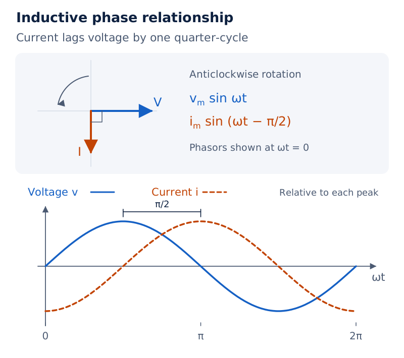
The left panel shows perpendicular voltage and current phasors, with current behind voltage. In the right panel, the current curve reaches its peak later than the voltage curve. The horizontal coordinate is the phase .
Drawn by One Young India. See Fig. 7.6 in your NCERT textbook
An inductor limits current without dissipating average power in the ideal case. Energy received during part of the cycle is returned during another part. The cycle-average power is zero, although instantaneous current and instantaneous power need not be zero.
Worked example 2. A pure inductor is connected to a rms, supply. Find its reactance and rms current.
Formula: , .
Substitute:
- Convert inductance:
- Calculate reactance:
- Calculate current:
Answer: The reactance is approximately , and the rms current is approximately . This is the ideal result with winding resistance neglected.
In a bulb-and-coil circuit, inserting an iron rod increases the coil's inductance. Its reactance therefore increases, leaving less voltage across the bulb and reducing its glow. The effect follows from the change in inductance at the same source frequency.
How does a capacitor respond to an AC voltage?
A capacitor connected to a DC source carries current while charging; after it becomes fully charged, the current falls to zero. With an AC source, repeated charging and discharging allow a continuing alternating current in the external circuit.
Let denote capacitance, measured in farads, , and the charge on a capacitor plate, measured in coulombs, . The ideal capacitor has voltage . Its current is the rate at which its charge changes.
Derivation: capacitive reactance and current lead
- Use the applied voltage to obtain the plate charge:
- Differentiate with respect to time:
- Rewrite in sine form:
- Define capacitive reactance and identify the current amplitude:
Result: Current in a pure capacitor leads voltage by radians. Capacitive reactance is measured in ohms and decreases when either capacitance or frequency increases. The capacitor draws zero average power over a complete cycle.
What the figure shows
Capacitive phase relationship
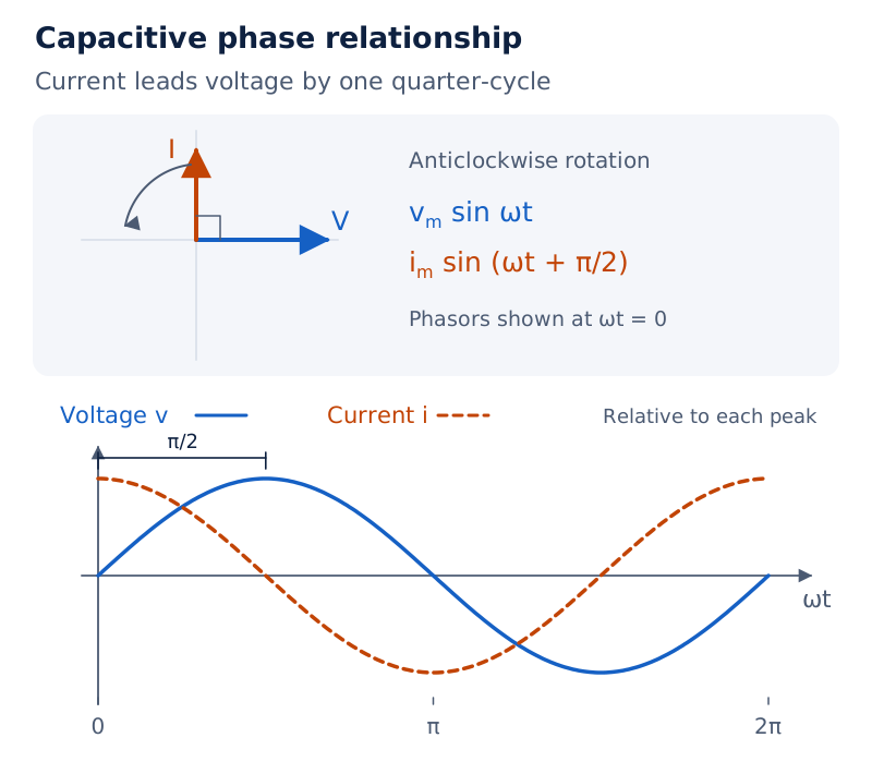
The current phasor is perpendicular to and ahead of the voltage phasor. The accompanying curves show the current maximum occurring before the voltage maximum, illustrating the quarter-cycle lead.
Drawn by One Young India. See Fig. 7.8 in your NCERT textbook
Worked example 3. A capacitor is connected to a rms, source. Find reactance, rms current and peak current, then describe the effect of doubling frequency at the same voltage.
Formula: , , .
Substitute:
- Convert capacitance:
- Calculate reactance:
- Find rms current:
- Find peak current:
Answer: Reactance is approximately , rms current , and peak current . Doubling frequency halves reactance and doubles both current values.
For a lamp in series with a capacitor, a DC source cannot maintain a steady glow after charging is complete. An AC source can maintain current. Reducing capacitance increases capacitive reactance and makes the lamp glow less brightly at the same AC supply.
How are impedance and phase found in a series LCR circuit?
A series LCR circuit contains an inductor, capacitor and resistor in one path. The instantaneous current is the same through all three elements. Their voltage drops have different phases, so adding their magnitudes directly gives an incorrect source voltage.
Derivation: the impedance triangle
Let , and denote the peak voltages across the resistor, inductor and capacitor respectively. Let denote circuit impedance, the combined opposition determining the current amplitude.
- Find the three voltage amplitudes from the common current:
- The resistor voltage is in phase with current. Inductor and capacitor voltages are oppositely directed in the phasor diagram and perpendicular to the resistor voltage. Therefore:
- Substitute the amplitudes and factor out squared current:
- Define impedance and solve for peak and rms current:
- With the current written as , the phase angle follows from the triangle:
Result: Impedance is measured in ohms. The sign of the net reactance fixes whether current leads or lags, while its square enters the magnitude of impedance. The phase convention must be stated before interpreting the sign.
| Reactance condition | Circuit character | Current relative to voltage |
|---|---|---|
| Predominantly capacitive | Leads, with | |
| Predominantly inductive | Lags, with | |
| Resonant series circuit | In phase, with |
What the figure shows
Series LCR voltage phasors
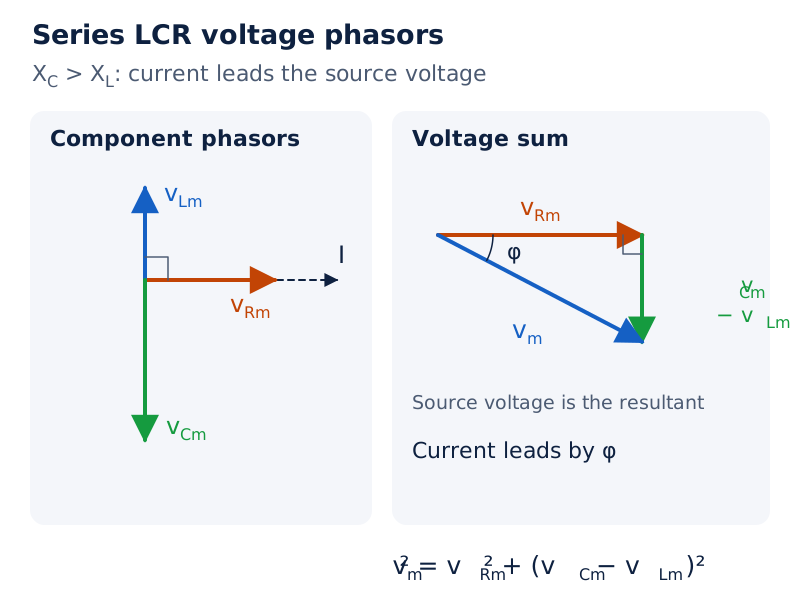
The resistor voltage phasor points along the current phasor. Inductor and capacitor voltage phasors point in opposite directions perpendicular to it. The second panel combines their resultant with the resistor voltage to give the source voltage phasor.
Drawn by One Young India. See Fig. 7.11 in your NCERT textbook
Worked example 4. A resistor and capacitor are in series across a rms, source. Calculate rms current and both component voltages.
Formula: , , , , .
Substitute:
- Calculate reactance:
- Calculate impedance:
- Find current:
- Find resistor voltage:
- Find capacitor voltage:
- Check the phasor sum:
Answer: The current is approximately , with component voltages approximately and . Their arithmetic sum exceeds the supply voltage because they differ in phase by .
When does resonance occur in a series LCR circuit?
Resonance occurs when a driven system responds strongly near its natural frequency. In a series LCR circuit, changing source frequency changes both reactances. At one frequency they become equal, so their opposing voltage phasors cancel.
Derivation: resonant frequency and maximum current
Let be the resonant angular frequency and the resonant frequency in hertz. Consider a fixed source voltage amplitude and a non-zero resistance.
- Set the inductive and capacitive reactances equal:
- Rearrange and take the positive root:
- Convert angular frequency to ordinary frequency:
- Substitute equal reactances into impedance and current:
Result: Impedance is minimum and current amplitude is maximum at resonance. Source voltage and current are in phase. The source voltage appears across the resistor, while the inductor and capacitor voltages cancel in the phasor sum.
What the figure shows
Current amplitude near resonance
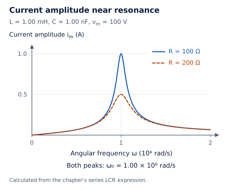
Two curves plot current amplitude against angular frequency. Both peak at the same frequency. The curve for the smaller resistance has a taller, narrower peak; the larger-resistance curve has a lower, broader peak.
Drawn by One Young India. See Fig. 7.14 in your NCERT textbook
Both inductance and capacitance are needed for this cancellation. A circuit containing only a resistor and an inductor, or only a resistor and a capacitor, cannot show this series resonance. Individual reactive voltages need not be zero when their resultant is zero.
How is resonance used?
A radio antenna receives signals from many stations. Varying the tuning capacitor changes the circuit's resonant frequency. When that frequency approaches the frequency of the desired signal, the corresponding current amplitude becomes large, enabling selection of that station.
The dimensionless quality factor, denoted by , is associated with a series resonant circuit and is given by . It must not be confused with the capacitor charge, denoted here by lowercase .
Worked example 5. A series circuit has , , and source peak voltage . Its frequency is adjustable. Find resonant frequency, impedance, rms current and average power at resonance.
Formula: , , , .
Substitute:
- Calculate angular frequency:
- Convert to frequency:
- Use resonant impedance:
- Convert peak voltage and find current:
- Calculate power:
Answer: Resonance occurs at approximately ; impedance is , rms current , and average power .
How do phase difference and power factor determine average power?
The average power taken from an AC source depends on voltage, current and their phase difference. The product of rms voltage and rms current alone gives the average power only when the two are in phase.
Derivation: average power in an AC circuit
- Multiply instantaneous voltage and current:
- Apply the product-to-sum identity:
- The second cosine averages to zero over a complete cycle:
- Replace peak quantities with rms quantities:
Result: The quantity is the power factor. For a series LCR circuit, , giving . Average energy dissipation occurs in the resistive element.
| Circuit | Power factor | Average power |
|---|---|---|
| Pure resistor | ||
| Pure inductor | ||
| Pure capacitor | ||
| Series LCR at resonance |
A current flowing with zero average power consumption is called a wattless current. Zero average power does not mean the instantaneous power is zero throughout the cycle. Ideal inductors and capacitors exchange energy with the source without net consumption over a complete cycle.
Why is a low power factor undesirable in transmission?
For fixed useful power and voltage, a smaller power factor requires a larger current. If denotes line resistance, transmission heating is . The larger current therefore increases energy loss in the line.
A suitable capacitor connected in parallel with an inductive load supplies a leading wattless current. This can cancel the lagging wattless component, improving the power factor. It is the perpendicular current components that cancel; the power-carrying component remains.
Worked example 6. A sinusoidal source of peak voltage and frequency drives a series circuit with , and . Find impedance, current phase, average power and power factor.
Formula: , , , , .
Substitute:
- Inductive reactance:
- Capacitive reactance:
- Impedance:
- Phase angle:
- Rms current:
- Power:
- Power factor, a dimensionless ratio:
Answer: Impedance is approximately , current lags by , power is approximately , and power factor is approximately . Rounding reactances gives the familiar approximate power factor .
How does a transformer change alternating voltage?
A transformer changes an alternating voltage using mutual induction. It contains two insulated coils wound on a soft-iron core. The input coil is the primary; the output coil is the secondary. Their electrical insulation does not prevent magnetic coupling through the core.
Let and denote primary and secondary turn counts. Let , , and denote their respective rms voltages and currents. An alternating primary current creates changing magnetic flux that links the secondary and induces an emf.
What the figure shows
Transformer windings
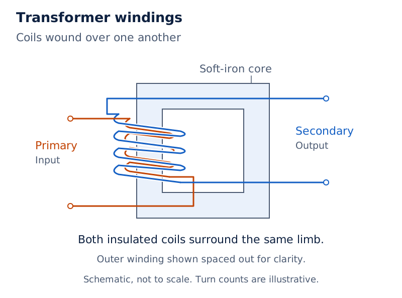
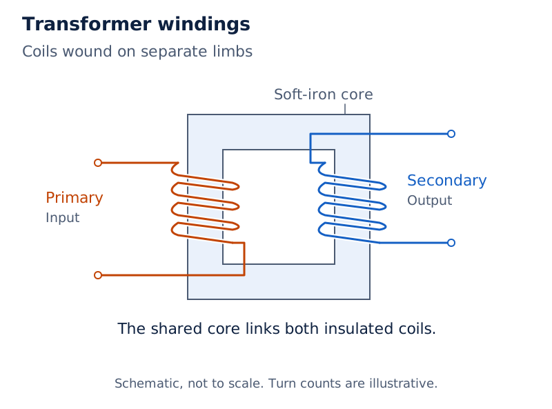
Both arrangements show a rectangular soft-iron core with primary and secondary connections. In the first, the coils are wound over one another on the same limb. In the second, they occupy separate limbs of the core.
Drawn by One Young India. See Fig. 7.16 in your NCERT textbook
Derivation: turns, voltage and current ratios
Let denote magnetic flux through each turn, measured in webers, , and , the induced primary and secondary emfs. Assume ideal flux linkage, negligible winding losses and consistent winding polarity.
- Apply Faraday's law to both coils:
- Divide their emf magnitudes; the same changing flux links each turn:
- For the ideal transformer, express the corresponding terminal-voltage ratio:
- With no energy loss, use the ideal power relation and combine ratios:
Result: A step-up transformer has more secondary turns, raising voltage while reducing current. A step-down transformer has fewer secondary turns, reducing voltage while increasing current. Raising voltage does not create energy, because the ideal current changes inversely.
Worked example 7. An ideal transformer has primary turns and secondary turns. Its input is rms at rms. Calculate output voltage and current.
Formula: , .
Substitute:
- Apply the dimensionless turns ratio:
- Use the inverse ratio for current:
- Check the voltage-current products:
Answer: Output voltage is and output current is . This is a step-up transformer, with the current reduced in the same proportion as the voltage increases.
What limits real transformers, and why are they used in transmission?
The ideal transformer relations neglect energy losses. Real transformers lose some energy in the windings and core, and not all primary flux necessarily links the secondary. Good construction reduces these losses but does not make an actual transformer perfectly lossless.
Which losses occur, and how are they reduced?
| Cause | Effect | Reduction method |
|---|---|---|
| Flux leakage | Some primary flux does not link the secondary because of core design or air gaps | Wind the primary and secondary coils over one another |
| Winding resistance | Current produces Joule heating in the wire | Use thick wire in high-current, low-voltage windings |
| Eddy currents | Changing flux induces currents that heat the iron core | Use a laminated core |
| Hysteresis | Repeated reversal of core magnetisation dissipates energy as heat | Choose core material with low hysteresis loss |
Lamination addresses eddy-current heating. Thick winding wire addresses resistive heating. These measures act on different losses and should not be exchanged when explaining transformer construction. Flux leakage reduces coupling, while hysteresis concerns repeated changes in the core's magnetisation.
Why is transmission carried out at high voltage?
For a given transmitted power, stepping up voltage reduces current. Since heating in transmission wires depends on current squared, the lower current reduces loss. A transformer therefore makes long-distance transmission more economical without increasing the energy supplied by the generator.
- The generator supplies electrical energy at an alternating voltage.
- A step-up transformer raises the transmission voltage and reduces the current required to carry the power.
- Energy travels along transmission lines with reduced resistive heating.
- Transformers near consumers step voltage down, with further reductions at distributing substations and utility poles.
The useful sequence is thus high voltage for transmission followed by lower voltage for distribution to consumers. The same mutual-induction principle supports both operations; the direction of voltage change depends on the relative numbers of primary and secondary turns.
Glossary
- Alternating current — Current that changes direction periodically, represented here by a sinusoidal function of time.
- Amplitude — The maximum magnitude attained by an oscillating voltage or current during its cycle.
- Rms current — Effective current equal to the direct current producing the same average heating in a resistor.
- Phasor — A rotating vector representing the amplitude and phase of a sinusoidally varying scalar quantity.
- Phase difference — Angular difference describing how the corresponding stages of two sinusoidal variations are displaced.
- Inductive reactance — Opposition offered by inductance to alternating current, increasing with inductance and source frequency.
- Capacitive reactance — Opposition offered by capacitance to alternating current, decreasing as capacitance or source frequency increases.
- Impedance — Combined opposition of circuit elements that determines the current amplitude for an applied alternating voltage.
- Resonance — Series-circuit condition in which equal inductive and capacitive reactances produce minimum impedance and maximum current.
- Power factor — Cosine of the phase difference between applied voltage and current, entering the average-power expression.
- Wattless current — Alternating current associated with zero average power consumption, as in a pure inductive or capacitive circuit.
- Transformer — Device using mutual induction between coils to change the magnitude of an alternating voltage.
- Hysteresis loss — Energy dissipated as heat when alternating magnetic fields repeatedly reverse the magnetisation of a transformer core.
Common errors and misconceptions
- Misconception: Zero average alternating current means zero heating. Correct: Resistive heating depends on , whose average is positive for a non-zero sinusoidal current.
- Misconception: The stated AC supply voltage is its peak value. Correct: It ordinarily means rms voltage; for a sinusoid, .
- Misconception: Current leads voltage in an inductor. Correct: It lags by in a pure inductor and leads by in a pure capacitor.
- Misconception: Rms voltages across series elements always add arithmetically. Correct: Their phases must be included; perpendicular voltage phasors combine by the Pythagorean theorem.
- Misconception: At resonance, the separate inductor and capacitor voltages vanish. Correct: Their equal, opposite phasors cancel; individual voltage amplitudes need not be zero.
- Misconception: A pure reactance dissipates power just like resistance. Correct: Pure inductance and capacitance have zero average power absorption over a complete cycle.
- Misconception: A step-up transformer increases both voltage and available energy. Correct: In the ideal relation, current decreases inversely and output power equals input power.
- Misconception: A laminated core prevents all transformer losses. Correct: Lamination reduces eddy-current loss; winding resistance, flux leakage and hysteresis need their own reduction measures.
Exam-style questions with model answers
Q1. Define rms current and relate it to the peak current of a sinusoid. [2 marks]
- Rms current is the direct current producing the same average heating in the same resistance as the alternating current.
- For peak current , rms current is . It is an effective value, distinct from the zero signed cycle-average.
Q2. Explain why a pure inductor carries AC but consumes no average power over a complete cycle. [3 marks]
- A changing current produces an induced emf that limits current. Inductive reactance is , where is angular frequency and is inductance.
- Current lags applied voltage by . Its instantaneous product with voltage can be positive or negative during the cycle.
- Energy is taken from and returned to the source. Since the power factor is , the average power is , with and denoting rms values.
Q3. A pure inductor is connected to a rms, source. Calculate reactance and rms current, and state the phase relation. [3 marks]
- Inductive reactance depends on both frequency and inductance. Using for frequency and for inductance,
- Divide rms voltage by reactance to obtain rms current:
- The current lags voltage by radians, or one quarter-cycle. This assumes negligible resistance in the winding; the reactance limits current without producing average Joule heating in an ideal inductor.
Q4. Derive the impedance and phase relation for a series LCR circuit driven by . Take the current as . [5 marks]
- Here and are peak voltage and current, is time, is angular frequency, and is current phase relative to voltage. The same current flows through all three series elements.
- For resistance , inductance and capacitance , the reactances are and . Peak element voltages are , and .
- The resistor voltage is along the current phasor. The reactive voltages oppose each other and are perpendicular to it. Thus
- Impedance and current amplitude follow:
- The triangle gives . A positive phase means current leads; a negative phase means it lags. This is the steady-state response.
Q5. Explain series resonance, derive its frequency and state its effect on impedance, current and power factor. [5 marks]
- Series resonance occurs when the inductive and capacitive reactances are equal. Their voltage phasors have equal magnitudes and opposite directions, so their resultant vanishes.
- Let be inductance, capacitance and resonant angular frequency. The condition is
- Rearranging gives , hence . The resonant frequency in hertz is .
- For resistance , impedance becomes , its minimum value. At fixed peak source voltage , peak current is maximum: .
- Current and source voltage are in phase, so the power factor is unity. Both an inductor and a capacitor are required for the cancellation. A series RL or RC circuit cannot show this resonance.
Q6. A sinusoidal source has peak voltage . It drives a series circuit with , and at resonance. Find the rms current and average power. [3 marks]
- At resonance, inductive and capacitive reactances cancel, so the impedance is . The supplied voltage is a peak value and must first be converted.
- Rms voltage is . Thus
- Current and source voltage are in phase, so average power is dissipated in the resistor:
Q7. Explain the principle of a transformer. Derive the ideal voltage and current ratios and explain why stepping up voltage conserves energy. [5 marks]
- A transformer works through mutual induction. An alternating primary current produces changing magnetic flux that links an insulated secondary coil and induces an emf.
- Let and be the primary and secondary turn counts, flux per turn and time. The induced emfs are and .
- Assuming common flux linkage and negligible winding losses, the rms terminal voltages satisfy .
- For an ideal lossless transformer, the corresponding rms currents satisfy . Combining relations gives .
- More secondary turns therefore produce higher secondary voltage but smaller secondary current. The inverse change preserves the ideal power balance. Real transformers have losses, so their output power is smaller than their input power.
Q8. Name four causes of transformer loss and give one way to reduce each. [4 marks]
- Flux leakage occurs when part of the primary flux misses the secondary. Winding the coils over one another improves linkage.
- Resistance in the windings causes Joule heating. Thick wire reduces this loss in high-current, low-voltage windings.
- Eddy currents induced in the iron core produce heating. A laminated core reduces their effect.
- Repeated magnetisation reversal produces hysteresis loss. Choosing a magnetic material with low hysteresis loss reduces this heating.
Key takeaways
- Sinusoidal rms values describe heating equivalence; they are smaller than peak values and differ from signed cycle-averages.
- Current is in phase with voltage in a pure resistor, lags in a pure inductor and leads in a pure capacitor.
- Inductive reactance increases with frequency, whereas capacitive reactance decreases when frequency or capacitance increases.
- Series circuit voltages must be combined with their phase differences; their rms magnitudes cannot generally be added arithmetically.
- Series resonance makes inductive and capacitive reactances equal, minimises impedance and maximises current for a fixed source voltage.
- Average AC power includes the power factor; ideal inductors and capacitors consume no net energy over a complete cycle.
- An ideal transformer changes voltage and current inversely through mutual induction while preserving the input-output power balance.
- High transmission voltage reduces current and line heating; practical transformer construction addresses winding, core and flux-linkage losses.
Test yourself
Why can an alternating current with zero signed average still heat a resistor?
Heating depends on squared current, so both current directions contribute positively to average resistive power.
What happens to inductive reactance when frequency increases at fixed inductance?
It increases in direct proportion to frequency, limiting current more strongly at the same applied voltage.
Which leads in a pure capacitor: current or voltage?
Current leads voltage by one quarter-cycle, corresponding to a phase difference of radians.
Why does a series RL circuit not show the LCR resonance discussed here?
It has no capacitor voltage to cancel the inductor voltage, so the required reactive cancellation cannot occur.
At resonance, are the separate inductor and capacitor voltages necessarily zero?
No. Their phasors have equal magnitudes and opposite directions; their resultant vanishes even when individual voltages do not.
Why does a lower power factor increase transmission loss for fixed useful power and voltage?
It requires a larger current, increasing the heating caused by the resistance of the transmission wires.
What happens to current in an ideal step-up transformer?
Secondary current decreases in inverse proportion to the voltage increase, maintaining the ideal power balance.
Which transformer loss is specifically reduced by laminating the core?
Lamination reduces eddy-current heating caused by currents induced in the core by the alternating magnetic flux.