
Electromagnetic Induction | CBSE Class 12 Physics Notes
On this page
Watch & explore
Start with a few high-quality watches, then dive into the notes below.
Learnacy Labs Try it hands-on: open the Electromagnetism lab
This note covers electromagnetic induction, Faraday and Henry’s experiments, magnetic flux, Faraday’s law, Lenz’s law and conservation of energy, motional electromotive force, mutual and self-inductance, magnetic energy, and the working of an alternating-current generator.
What do Faraday and Henry’s experiments show about induction?
Electromagnetic induction connects a changing magnetic environment with an induced electromotive force. Moving charges produce magnetic fields; the complementary discovery is that changing magnetic flux can produce an electric current in a closed conducting circuit.
The experiments of Michael Faraday in England and Joseph Henry in the USA established this connection around 1830. Their results explain how generators convert mechanical energy into electrical energy and why a changing current in one coil can affect another nearby coil.
How does a moving magnet affect a coil?
Connect a conducting coil to a galvanometer, an instrument that detects current. Push the north pole of a bar magnet towards the coil. The galvanometer deflects while the magnet moves. Hold the magnet stationary and the deflection disappears.
Withdraw the magnet and the deflection reverses. Moving the south pole in the same way reverses the corresponding deflections. Faster movement produces a larger deflection. Moving the coil while keeping the magnet fixed gives the same kind of effect: relative motion matters in this arrangement.
Can two stationary coils demonstrate induction?
Yes. Call the detecting coil and the nearby source coil . Connect the first to a galvanometer and the second to a battery through a tapping key. Both coils can remain stationary throughout the experiment.
- Press the key. Current in the source coil rises, changing the magnetic field through the detecting coil.
- The galvanometer shows a momentary deflection while this change occurs.
- Keep the key pressed. Once the source current becomes steady, the galvanometer returns to zero.
- Release the key. The falling source current produces a momentary deflection in the opposite direction.
Inserting an iron rod along the common axis of the coils greatly increases the deflection. Alternatively, a current-carrying source coil can replace the bar magnet in the moving-magnet experiment. Moving it towards or away from the detecting coil also induces current.
What the figure shows
Stationary coils and a tapping key
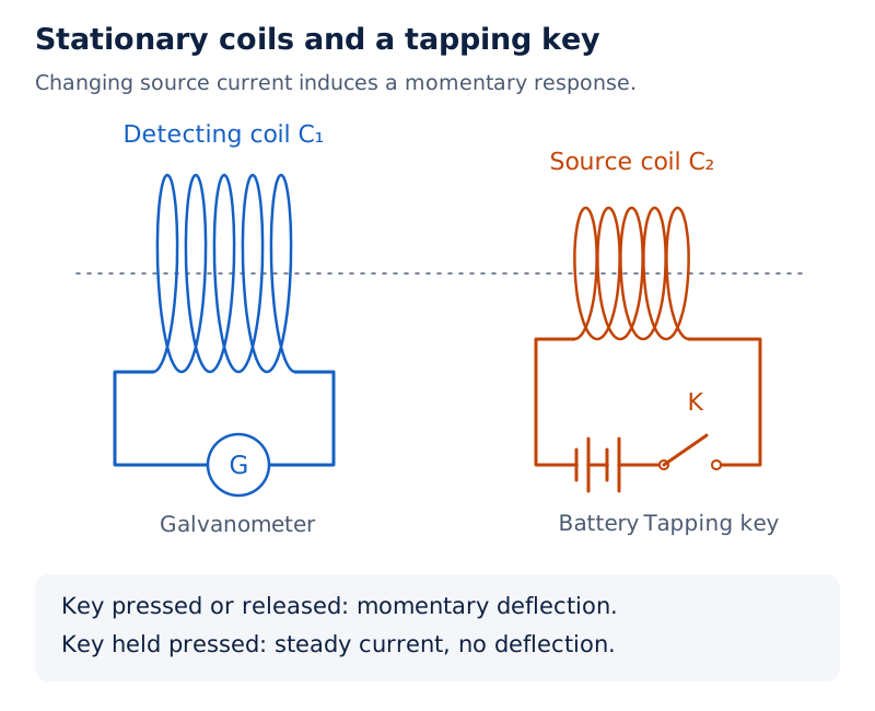
Two separated coils share a dotted horizontal axis. The larger detecting coil connects to a galvanometer labelled G. The other coil connects to a battery and a key labelled K.
Drawn by One Young India. See Fig. 6.3 in your NCERT textbook
Relative motion is not essential in every induction experiment. The stationary-coil experiment isolates the central condition: magnetic flux through the detecting coil must change. A steady magnetic field, however strong, does not by itself maintain an induced current in a fixed loop.
What is magnetic flux and how is it calculated?
Definition: Magnetic flux through a plane surface in a uniform magnetic field is the scalar product of the magnetic field vector and the area vector of the surface.
Let denote magnetic flux, the magnetic field vector, and the area vector perpendicular to the surface. Their magnitudes are and . Let be the angle between these two vectors.
The area vector points along a normal to the plane. Consequently, the angle in this equation is measured from that normal, not from the plane itself. Choosing an area-vector direction also establishes the sign convention for the flux.
How does orientation change flux?
| Orientation of the area vector | Angle | Magnetic flux |
|---|---|---|
| Parallel to the field | ||
| Perpendicular to the field | ||
| Opposite to the field |
Magnetic flux is a scalar, even though it is calculated from two vectors. Its sign distinguishes the two orientations relative to the chosen normal. A negative flux does not mean a negative magnetic-field magnitude or a negative geometrical area.
The SI unit of magnetic flux is the weber, symbol . The SI unit of magnetic field is the tesla, symbol . Their relation is
What changes for a curved surface or a non-uniform field?
Divide the surface into small area elements. Let represent the area vector of the element indexed by , and let be the field at that element. Add their individual contributions:
This accounts for variations in both field direction and surface orientation. The simple product for a plane in a uniform field is a special case. Flux can change through a change in field strength, surface area, orientation, or a combination of these changes.
What the figure shows
Area vector and magnetic flux
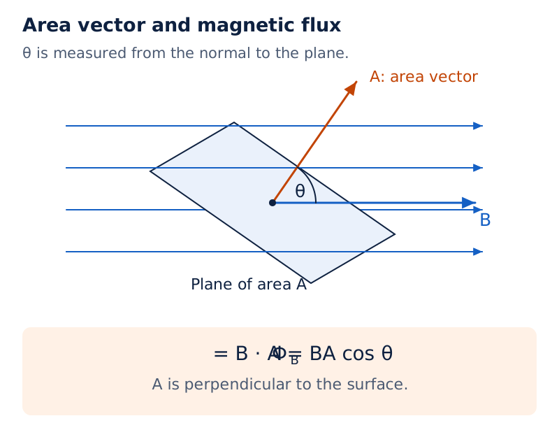
Parallel field arrows pass through an inclined plane. The field vector and the area vector are labelled separately, with the angle marked between their directions.
Drawn by One Young India. See Fig. 6.4 in your NCERT textbook
How does Faraday’s law determine induced emf and current?
Faraday’s law states that the magnitude of the induced electromotive force equals the time rate of change of magnetic flux through the circuit. Write for induced emf and for time. For a single turn:
For a closely wound coil with turns, provided the same flux passes through each turn, the total flux linkage is . Keeping the number of turns constant gives
The SI unit of induced emf is the volt, symbol , with The minus sign specifies the opposing sense of induction; it is interpreted using Lenz’s law.
When is the average-value formula appropriate?
Let be the final flux minus the initial flux per turn, and let be the elapsed time. The average induced emf, denoted by , is
This equals the instantaneous emf throughout the interval only when the rate of flux change remains constant. In a closed resistive circuit, let denote current and resistance. Then . The SI unit of current is the ampere, symbol . Resistance is measured in ohms, symbol .
Worked example 1. A square loop of side and resistance stands vertically in the east-west plane. A horizontal north-east field of decreases uniformly to zero in . Find the induced emf and current magnitudes.
Formula: Use and , with . The angle between the field and the loop’s normal is .
Substitute:
- The area is .
- The initial flux is , where the subscript means initial.
- The final flux is zero, so . Hence .
- The current is .
Answer: Approximately and , or and . The steady part of the Earth’s field contributes no changing flux.
More turns produce a larger induced emf for the same per-turn flux-change rate. Increasing a steady flux alone does not guarantee an emf: the rate of change, rather than the flux value, is the determining quantity.
How does Lenz’s law connect current direction with energy conservation?
Definition: Lenz’s law states that the polarity of induced emf tends to produce a current opposing the change in magnetic flux that produced it.
The key expression is opposes the change. If the original flux increases, the induced current produces a magnetic effect that resists the increase. If the original flux decreases, the induced current tends to maintain it. Thus the induced field need not oppose the original field.
What happens when a north pole approaches or recedes?
| Magnet’s motion | Near face of the coil | Current viewed from the magnet |
|---|---|---|
| North pole approaching | North polarity, opposing approach | Anticlockwise |
| North pole receding | South polarity, opposing withdrawal | Clockwise |
The viewing direction must be stated when using clockwise or anticlockwise. Reversing the side from which a loop is viewed reverses these descriptions. First identify the change of flux, then determine the induced magnetic effect, and finally infer the current direction.
Why would the opposite direction violate conservation of energy?
If an approaching north pole induced a south pole on the coil’s near face, the magnet would be attracted further towards it. This would increase the flux change and reinforce the attraction. Its kinetic energy could then grow without a corresponding expenditure of energy.
The actual induced current produces repulsion during approach. External work is required to push the magnet towards the coil. In the resistive circuit, that supplied energy is dissipated as Joule heating. During withdrawal, attraction similarly opposes the motion.
Note: An open circuit can have an induced emf across its ends. It does not support the circulating conduction current of a closed loop. Lenz’s law can still determine the polarity of that emf.
A loop entering a region of perpendicular magnetic field experiences increasing flux; one leaving experiences decreasing flux. A loop moving wholly within a uniform field without changing its area or orientation has unchanged flux and no induced emf from that translation.
Energy conservation therefore provides a physical check on a direction answer. In the moving-magnet arrangement, the induced effect resists the motion responsible for the change. It does not supply an unlimited source of mechanical or electrical energy.
How does rotating a coil change its flux?
A coil can experience changing flux even when both its area and the external field strength remain constant. Rotation changes the angle between its area vector and the magnetic field. The orientation factor in the flux equation therefore changes with time.
A half-turn takes an initially aligned area vector into the opposite direction. The initial and final fluxes have equal magnitudes but opposite signs. Their difference must be calculated algebraically before its magnitude is used to find the average emf.
How should a half-turn calculation be organised?
Worked example 2. A circular coil has radius , turns and resistance . Its plane is initially perpendicular to the Earth’s horizontal field of . It rotates through about its vertical diameter in . Estimate the average emf and current magnitudes.
Formula: Let be the coil radius and the circle constant. Use , , and , where denotes average current.
Substitute:
- The area is .
- The initial flux per turn is .
- The final flux, denoted by , is . Thus .
- The average emf magnitude is .
- The average current magnitude is .
Answer: Approximately and . These are average estimates for the half-turn, not the instantaneous values throughout the motion.
The instantaneous emf depends on the angular position and the rate of rotation at that instant. Knowing only the total angle and elapsed time determines the average flux-change rate, but does not specify the full variation of emf during the turn.
This distinction also matters when interpreting magnetic flux. A large flux can coincide with a small rate of flux change. During uniform rotation, emf reaches its greatest magnitude when the flux passes through zero, rather than when the flux magnitude is greatest.
How is motional emf produced in a moving conductor?
Motional emf is induced when a conductor moves through a magnetic field in an appropriate direction. Consider a straight rod sliding on conducting rails, forming one side of a rectangular closed circuit in a uniform, time-independent field perpendicular to its plane.
Let be the rod length, the changing width of the rectangle, and the rod’s speed. The rod moves so the width decreases. Assume the rod, its velocity and the magnetic field are mutually perpendicular.
Derivation: Emf in a sliding rod
- The enclosed area is , so the flux is .
- Apply Faraday’s law: .
- Since field strength and rod length remain constant, .
- For the stated decreasing width, . Hence , with the current sense fixed by Lenz’s law.
Result: The emf magnitude is for this perpendicular arrangement. The field itself does not have to change: changing the enclosed area is sufficient.
How does the magnetic force separate charges?
Let denote a positive charge carried along with the rod, the magnetic-force magnitude on it, and the work associated with moving it along the rod. The charge-carrier argument gives:
- The magnetic force magnitude is for perpendicular velocity and field.
- The work over the rod length is .
- Work per unit charge gives the emf: .
For a stationary conductor in a changing magnetic field, this motion-based argument is insufficient. A time-varying magnetic field generates an electric field, which can act on charges even when the conductor is stationary.
Why does a rotating rod require integration?
Let be angular speed, distance from the rotation axis, and the rod’s full length. Different elements move at different speeds, so the tip speed cannot be assigned to the whole rod.
- An element at distance has speed .
- An element of length contributes to the emf magnitude.
- Adding contributions gives .
Worked example 3. A metallic rod rotates about one end at . Its other end touches a circular metallic ring. A uniform field lies along the rotation axis. Find the emf magnitude between the centre and ring.
Formula: Let denote rotation frequency. Use and .
Substitute:
- The angular speed is .
- The emf is , treating the radian as dimensionless.
- Evaluating gives .
Answer: The emf magnitude is approximately .
Worked example 4. A wheel has ten metallic spokes, each long. It rotates at in a plane normal to the Earth’s horizontal magnetic field of , where denotes gauss and . Find the axle-to-rim emf magnitude.
Formula: Each spoke behaves as a rotating rod, with .
Substitute:
- The frequency is , giving .
- The field is .
- The emf is .
Answer: Approximately . The spokes connect in parallel between axle and rim, so their emfs are not added as ten series sources.
What is mutual inductance between two coils?
Mutual induction occurs when a changing current in one coil induces emf in another. For fixed geometry and the proportional magnetic response considered here, the flux linkage of the receiving coil is proportional to the current in the source coil.
Let be the receiving coil’s turn count, its flux per turn due to the source coil, and the source-coil current. Define , its mutual inductance with respect to the source coil, by
The SI unit of inductance is the henry, symbol , with Inductance is scalar and depends on geometry and the magnetic properties of the medium.
Derivation: Mutual inductance of long coaxial solenoids
Take two long coaxial solenoids of common length , with inner radius , outer radius , and turn densities and . Here is the permeability of free space. Neglect end effects and assume .
- The outer solenoid carrying current produces the nearly uniform internal field , where denotes that field magnitude.
- The inner coil has turns and receives flux per turn .
- Its flux linkage is .
- Compare with the definition to obtain .
- Reverse the roles of the coils. The inner coil’s field is confined approximately to its own cross-section, giving , where is the reverse mutual inductance.
Result: Both arrangements share a mutual inductance . Use the inner cross-sectional area in this geometry. If the interior has relative permeability , the expression becomes .
What the figure shows
Coaxial solenoids
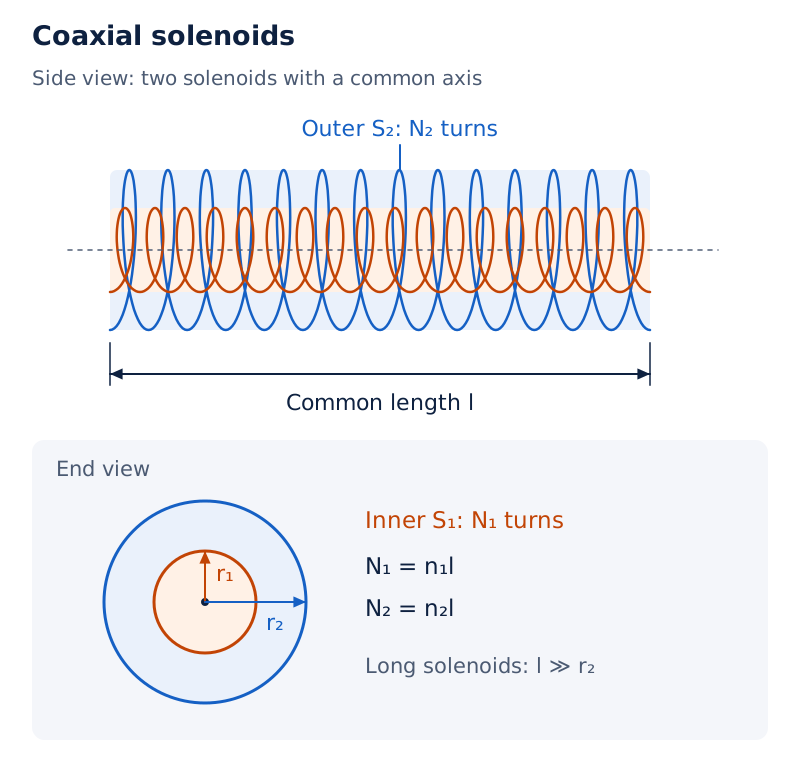
A smaller solenoid lies inside a larger one along the same axis. The drawing labels their common length, their two radii, their turn counts and the two solenoids separately.
Drawn by One Young India. See Fig. 6.12 in your NCERT textbook
How does changing current induce emf in the second coil?
Let be the receiving coil’s induced emf. For constant mutual inductance, applying Faraday’s law to its flux linkage gives:
- Write the flux linkage as .
- Differentiate with respect to time: .
- Apply the negative sign from Faraday’s law: .
Separation and relative orientation affect mutual inductance. The equality of the two mutual inductances is useful when calculating the flux in one direction is easier than in the reverse direction; the numerical result can then serve both directions.
What is the mutual inductance of two concentric circular coils?
For two single-turn circular coils with coinciding centres, let their radii be and , with . Their axes coincide. The field of the larger coil is approximately uniform over the much smaller coil.
- A current in the larger coil produces a central field .
- The flux through the smaller coil is .
- Compare this with for a single turn to obtain .
- Reciprocity gives , avoiding the harder calculation of the small coil’s non-uniform field over the larger coil.
The small-radius approximation is essential here. The expression is not a general result for arbitrary pairs of circular coils with comparable radii or different relative orientations.
What is self-inductance and why does it oppose current changes?
Self-induction occurs when a changing current alters the magnetic flux linked with its own coil and induces emf in that same coil. Let denote self-inductance. For the proportional response considered here, its defining relation is
When self-inductance remains constant, Faraday’s law gives This back emf opposes the change in current. During current growth it resists the growth; during current decay it tends to maintain the current.
Derivation: Self-inductance of a long solenoid
Consider an air-core solenoid with cross-sectional area , length , and turns per unit length. Neglect the field near its ends and use the uniform internal field approximation.
- The magnetic field produced by current is .
- The number of turns is , and each turn has flux .
- The total flux linkage is .
- Divide by current to obtain .
Result: For a core of relative permeability , . Thus the inductance depends on coil geometry and the core’s magnetic properties in this model.
The role of self-inductance resembles inertia in mechanics. A larger inductance requires a larger opposing emf for a given rate of current change. This analogy concerns resistance to change, rather than the resistance responsible for Joule heating.
Worked example 5. Current in a circuit falls from to zero in . The average induced emf magnitude is . Estimate the circuit’s self-inductance.
Formula: For constant inductance, , where denotes the final current minus the initial current.
Substitute:
- The current-change magnitude is .
- The average rate magnitude is .
- The inductance is .
Answer: A change of under these conditions implies . The induced emf tends to sustain the falling current.
How do mutual and self-induction differ?
| Feature | Self-induction | Mutual induction |
|---|---|---|
| Source of changing flux | Changing current in the same coil | Changing current in another coil |
| Coefficient | Self-inductance | Mutual inductance |
| Emf relation | ||
| SI unit | Henry | Henry |
If both nearby coils carry changing currents, self-induction and mutual induction both contribute. Let and denote the first coil’s self-inductance and current. With consistent winding conventions and constant inductances, its emf is .
How is energy stored in an inductor’s magnetic field?
Establishing a current requires work against the back emf. If resistive losses are ignored, this work is stored as magnetic energy. Let denote the energy stored after the current rises from zero to its final value .
Derivation: Energy stored in an inductor
Assume constant self-inductance and an initially zero current. Use for the current during the build-up, distinguishing this integration variable from the final current.
- The applied emf needed to balance the inductive opposition is , where denotes this supplied emf.
- The rate of external work is .
- The incremental work is therefore .
- Integrate from zero current to the final current: .
Result: Magnetic energy is proportional to inductance and to the square of current. The SI unit of magnetic energy is the joule, symbol .
How is this energy written in terms of field strength?
For the long air-core solenoid, substitute its inductance and the current expressed through its field. Let denote the solenoid’s interior volume and its magnetic energy per unit volume.
- From , obtain .
- Substitute into the energy expression: .
- Since , divide by volume: .
For comparison, the electric-field energy density in free space is , where is electric energy per unit volume, is the permittivity of free space, and is electric-field magnitude. Both energy densities depend on the square of the corresponding field.
The energy derivation deliberately excludes resistive heating. In a circuit with resistance, the source must also supply the energy dissipated as heat. The magnetic energy expression describes the stored part, rather than the entire energy supplied under all circumstances.
How does an AC generator produce an alternating emf?
An AC generator converts mechanical energy into electrical energy by rotating a coil in a magnetic field. Its rotating coil, called the armature, is mounted on a shaft whose axis is perpendicular to the field. Slip rings and brushes connect its ends to an external circuit.
What the figure shows
AC generator
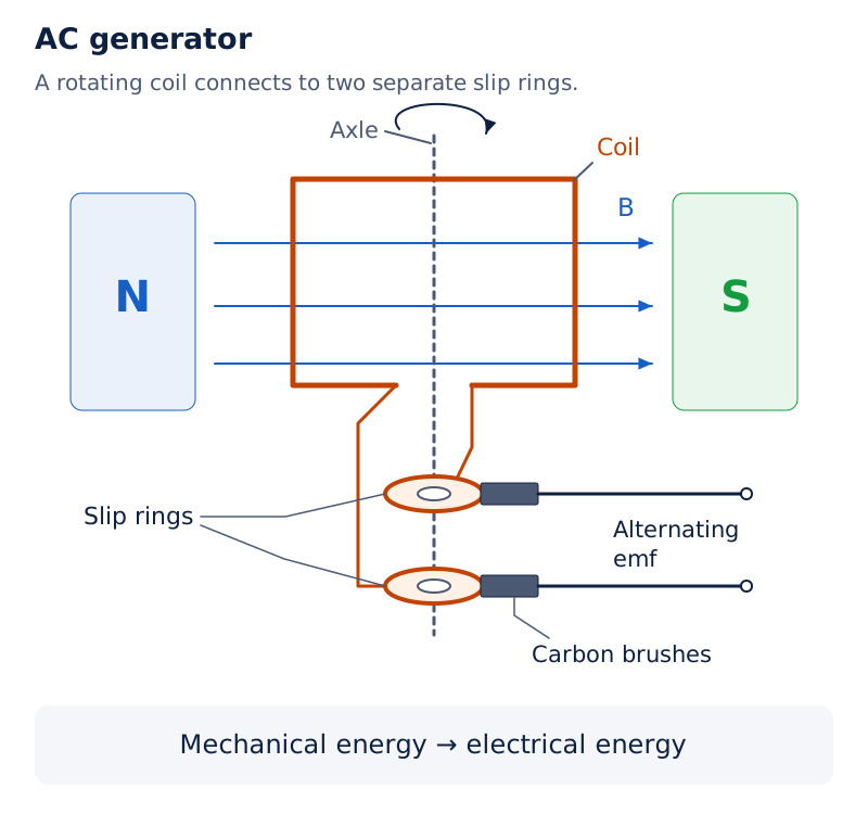
A coil and axle lie between magnetic poles marked N and S. The coil ends lead to two slip rings contacted by carbon brushes. The external leads are labelled as supplying alternating emf.
Drawn by One Young India. See Fig. 6.13 in your NCERT textbook
Derivation: Instantaneous generator emf
Let the coil have turns, area , and constant angular speed in a uniform field . Choose zero time when the area vector is parallel to the field.
- The angle at time is .
- The magnetic flux per turn is .
- Faraday’s law gives .
- Differentiate to obtain .
- Define the peak emf as . Hence , or because .
Result: The emf changes sign periodically. In a closed circuit this produces alternating current. Its peak magnitude depends on the turn count, field strength, coil area and angular speed.
How do flux and emf vary during a revolution?
The emf is zero when the area vector is parallel or antiparallel to the field. Its positive and negative extremes occur when the area vector is perpendicular to the field. The decisive quantity is the rate of flux change.
What the figure shows
Alternating emf during coil rotation
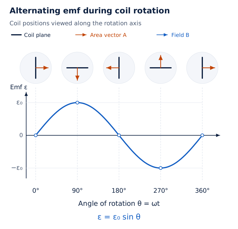
Five successive coil positions are aligned with a sinusoidal emf curve. The curve crosses zero at , and , reaches a positive peak at , and a negative peak at .
Drawn by One Young India. See Fig. 6.14 in your NCERT textbook
Worked example 6. A stationary bicycle drives a coil of turns and area at half a revolution per second. A uniform magnetic field is perpendicular to the rotation axis. Find the maximum generated voltage.
Formula: The peak emf is .
Substitute:
- The angular speed is .
- The peak emf is .
- Evaluating gives .
Answer: The maximum voltage is approximately . This is the peak value, not a constant output voltage throughout the revolution.
The mechanical drive can come from falling water, steam produced using coal or other heat sources, or steam generated using nuclear fuel. These arrangements supply energy to the generator; electromagnetic induction provides the conversion mechanism.
Glossary
- Electromagnetic induction — Production of induced emf through a change in magnetic flux associated with a circuit.
- Magnetic flux — Scalar quantity obtained by adding the magnetic field’s contributions through the elements of a surface.
- Area vector — Vector perpendicular to a surface element, with magnitude equal to the element’s area.
- Induced emf — Electromotive force produced by changing magnetic flux or appropriate conductor motion through a magnetic field.
- Flux linkage — Product of turn count and flux per turn when the same flux links every turn.
- Faraday’s law — Law relating induced emf to the time rate of change of magnetic flux linkage.
- Lenz’s law — Rule determining induced polarity by opposition to the magnetic flux change responsible for induction.
- Motional emf — Emf developed through appropriate motion of a conductor in a magnetic field.
- Mutual inductance — Coefficient relating flux linkage in one coil to the current producing it in another coil.
- Self-inductance — Coefficient relating a coil’s own magnetic flux linkage to the current flowing through it.
- Back emf — Self-induced emf that opposes an increase or decrease of current in the circuit.
- Armature — Generator coil mechanically rotated in a magnetic field to produce a changing flux linkage.
Common errors and misconceptions
- Misconception: A strong magnetic field must induce a current. Correct: A fixed loop in a steady field has no changing flux, however large that field is.
- Misconception: Magnetic flux uses the angle between field and plane. Correct: The angle is between the field and the area vector normal to the plane.
- Misconception: Lenz’s law makes the induced field oppose the original field in every case. Correct: It opposes the change of flux, so it can reinforce a decreasing original flux.
- Misconception: An open circuit cannot develop induced emf. Correct: Emf can appear across open ends even though a circulating conduction current does not flow.
- Misconception: A half-turn changes the flux from its initial value to zero. Correct: For an initially aligned area vector, the final flux has the opposite sign and equal magnitude.
- Misconception: A rotating rod moves everywhere at its tip speed. Correct: Local speed increases with distance from the axis; integrate contributions along the rod.
- Misconception: Ten spokes produce ten times the axle-to-rim emf. Correct: The spokes are parallel connections between the same axle and rim, so their emfs do not add in series.
- Misconception: Generator emf is greatest when magnetic flux is greatest. Correct: For uniform rotation, peak emf occurs at zero flux, where its rate of change has greatest magnitude.
Exam-style questions with model answers
Q1. State Lenz’s law and explain the negative sign in Faraday’s law. [2 marks]
- Lenz’s law states that induced polarity tends to produce a current opposing the change of magnetic flux that caused it.
- The minus sign in Faraday’s law expresses this opposing sense, rather than specifying a negative emf magnitude.
Q2. Explain how two stationary coils, a battery, a tapping key and a galvanometer demonstrate electromagnetic induction. State what happens when the key is pressed, held pressed and released. [3 marks]
- Connect the detecting coil to the galvanometer and the nearby source coil to the battery through the tapping key. Pressing the key builds up the source current and changes flux through the detecting coil, producing a momentary deflection.
- Holding the key pressed makes the source current steady. Flux stops changing, so the detecting current disappears.
- Releasing the key reduces source current to zero. The opposite flux change produces a momentary deflection in the opposite direction, although neither coil moves.
Q3. Derive the motional emf across a rod of length sliding so that a rectangular loop’s width decreases at speed . A uniform constant field is normal to the loop, and rod, velocity and field are mutually perpendicular. [5 marks]
- The rod and fixed rails form a closed rectangular circuit. Its enclosed area is , where denotes area. Since the field is normal to the loop, its flux is .
- Faraday’s law relates the induced emf to the negative flux-change rate: , where is time.
- The field and rod length remain constant, so differentiation gives . The change comes entirely from the changing width.
- Because the width decreases, . Substitution gives for the chosen orientation, and therefore an emf magnitude .
- Lenz’s law determines its physical polarity: any resulting current opposes the decrease of flux. This derivation shows that a time-independent field can produce emf when circuit area changes.
Q4. A circuit’s current falls from to zero in , producing an average induced emf of magnitude . Assuming constant self-inductance, calculate it and explain the emf’s effect. [3 marks]
- The average current-change magnitude is . Over the stated interval the average rate magnitude is .
- Use the magnitude of the self-induction relation: . Substitution gives .
- The negative sign in the signed emf relation expresses opposition to change. Here the current decreases, so the induced emf tends to maintain its original direction rather than accelerate its disappearance.
Q5. Derive the energy stored when current in an initially unenergised inductor of constant self-inductance increases from zero to . Neglect resistive losses. [5 marks]
- Let denote the current during its build-up and the external work done. The source must work against the self-induced back emf, whose magnitude during increasing current is .
- The applied emf required to balance that inductive opposition is . Electrical power is applied emf times current, so .
- Multiply by the time increment to obtain . This is the work needed for the corresponding increment of current.
- Integrating gives , since inductance is constant and the initial current is zero.
- With resistive losses excluded, this work remains stored as magnetic energy: . Its SI unit is the joule. The dependence on current is quadratic, resembling the dependence of mechanical kinetic energy on speed.
Q6. A generator coil has turns and area , and rotates at in a uniform field perpendicular to its rotation axis. Calculate the peak emf and explain why the output alternates. [3 marks]
- The angular speed is . This uses the given frequency of rotation, not an assumed electrical frequency.
- The peak emf is .
- Rotation changes the flux periodically. With the area vector initially parallel to the field, . The sine changes sign each half-cycle, reversing emf polarity and therefore giving an alternating output.
Key takeaways
- Electromagnetic induction depends on changing magnetic flux; a large steady field through a fixed loop does not suffice.
- Magnetic flux uses the angle between the field and the area vector, which is normal to the surface.
- Faraday’s law gives induced emf from the rate of flux-linkage change; Lenz’s law determines its opposing polarity.
- A half-turn reverses the sign of initially maximum flux; average emf must use the full initial-to-final change.
- Motional emf can arise in a constant magnetic field because conductor motion changes the circuit’s enclosed area.
- Self-induction concerns a coil’s own changing current, while mutual induction connects changing current in one coil with another.
- Work done against inductive opposition is stored as magnetic energy when resistive losses are excluded from the calculation.
- A uniformly rotating generator coil produces a sinusoidal emf whose magnitude peaks when its flux passes through zero.
Test yourself
Why does a stationary magnet beside a fixed coil produce no sustained induced current?
The magnetic flux through the coil remains constant, so its time rate of change is zero.
Which angle appears in the expression for magnetic flux through a plane?
The angle between the magnetic field and the area vector perpendicular to the plane.
What happens to galvanometer deflection when the relative motion of magnet and coil is reversed?
The deflection reverses, indicating reversal of the direction of the induced current.
Why can pressing a key induce current in a nearby stationary coil?
The source current changes, changing the magnetic field and hence the flux through the nearby coil.
Why must contributions be integrated along a rotating rod?
Different elements have different speeds because their distances from the rotation axis differ.
What does self-induced emf do while a current is decreasing?
It opposes the decrease and tends to maintain current in its existing direction.
What determines a solenoid’s self-inductance in the linear model?
Its geometry, including turn density, length and cross-sectional area, and the magnetic permeability of its core.
At which orientations is a uniformly rotating generator coil’s emf magnitude greatest?
When its area vector is perpendicular to the field, the flux-change rate has greatest magnitude.