
Magnetism and Matter | CBSE Class 12 Physics Notes
On this page
Watch & explore
Start with a few high-quality watches, then dive into the notes below.

Learnacy Labs Try it hands-on: open the Magnetism lab
This note covers bar magnets, magnetic field lines, equivalent solenoids, dipole fields, torque and potential energy, Gauss’s law for magnetism, magnetisation, magnetic intensity, susceptibility, permeability, diamagnetism, paramagnetism, ferromagnetism and numerical applications.
What does a bar magnet reveal about magnetic poles?
Poles and orientation
A freely suspended bar magnet points approximately north-south. Its north-seeking end is called the north pole; its south-seeking end is called the south pole. These names describe the observed orientation of the suspended magnet.
Two north poles repel, and two south poles repel. A north pole and a south pole attract. The Earth itself behaves as a magnet, with its field directed approximately from geographic south towards geographic north.
Definition: A magnetic dipole is the simplest magnetic element, represented by a bar magnet or a current loop. A bar magnet has both a north pole and a south pole.
Why cutting does not isolate a pole
Cutting a magnet across its length produces two smaller magnets. Cutting it along its length also produces two magnets, each possessing both poles. The new pieces have weaker magnetic properties, but neither becomes an isolated north or south pole.
Magnetic monopoles, meaning isolated magnetic poles, are not known to exist. This differs from electric charge: an isolated positive or negative electric charge can exist. The difference later appears directly in the two forms of Gauss’s law.
Iron filings scattered over glass above a bar magnet arrange themselves into a characteristic pattern. The arrangement suggests two polar regions and gives a visual indication of the surrounding magnetic field. A current-carrying solenoid produces a similar pattern.
What the figure shows
Iron filings around a bar magnet
The photograph shows filings arranged in curved bands between two concentrated regions. The pattern outlines the field surrounding the magnet rather than two isolated sources of magnetic field.
See Fig. 5.1 in your NCERT textbook
Attraction alone does not establish that two objects are permanent magnets. A magnet can also attract an initially unmagnetised iron object by inducing magnetisation. Repulsion between appropriately presented ends establishes that both bars are magnetised.
How do magnetic field lines represent a magnetic field?
Direction, strength and continuity
A magnetic field line is a visual representation of the field. Its tangent at a point gives the direction of the net magnetic field there. We write the magnetic field vector as , with magnitude . The SI unit of magnetic field is tesla, written .
The greater the concentration of field lines crossing unit area, the greater the field strength. Near a bar magnet’s poles, the lines are more closely crowded. Field lines cannot intersect because an intersection would assign two different directions to the field at one point.
Magnetic field lines form continuous closed loops. Outside a bar magnet they run from the north pole towards the south pole; inside, they return from south to north. They do not begin or end at either pole.
What the figure shows
Magnetic and electric dipole patterns
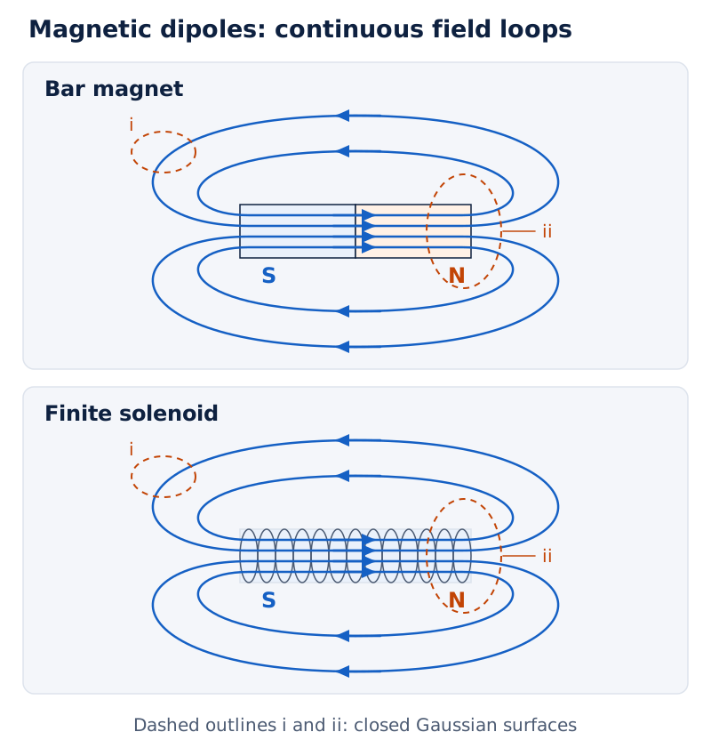
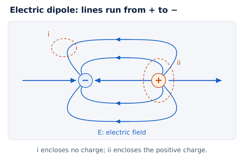
Three panels compare a bar magnet, a finite solenoid and an electric dipole. The magnetic diagrams show returning lines through their interiors. Closed Gaussian surfaces labelled i and ii surround selected regions.
Drawn by One Young India. See Fig. 5.2 in your NCERT textbook
What a compass measures
A small compass placed at different positions gives the local field direction through its orientation. Repeating this observation allows a field pattern to be mapped. The compass responds to the net field at each position, rather than to one selected source alone.
Field lines are not generally lines of force on a moving charge. If is the charge, its velocity and the magnetic force, then . A non-zero magnetic force is perpendicular to the field.
Note: Do not draw solenoid field lines as straight lines that stop abruptly at its ends. They curve outside and return. Similarly, field lines near the edges of pole pieces exhibit fringing rather than remaining perfectly straight everywhere.
How can a solenoid behave like a bar magnet?
The equivalent-solenoid description
A current loop behaves as a magnetic dipole. A solenoid consists of many such loops, and its external field resembles that of a bar magnet. Similar compass deflections around the two systems provide an experimental way of comparing their field patterns.
A bar magnet can therefore be represented by an equivalent arrangement of circulating currents. Cutting a magnet is analogous to cutting a solenoid into smaller solenoids: each piece still produces a dipole pattern, with field lines returning through its interior.
Let denote the magnetic dipole moment, and its magnitude. For a closely wound solenoid, let be its number of turns, the current and its cross-sectional area. Its moment is .
The SI unit of magnetic moment is ampere square metre, , equivalently joule per tesla, . Moment points along the solenoid’s axis, in the direction corresponding to the magnet’s south-to-north direction.
Worked example 1. A closely wound solenoid has turns, cross-sectional area , and current . Find its magnetic moment.
Formula: .
Substitute:
Answer: The magnetic moment is , directed along the solenoid’s axis. Its dipole-like external field explains the comparison with a bar magnet.
Where the analogy needs care
The bar magnet analogy does not mean that every current configuration has identifiable north and south ends. A toroid, for example, confines its magnetic field within the winding region. Its field lines close without giving the arrangement the non-zero net dipole moment of a bar magnet.
The magnetic moment of an equivalent solenoid is chosen to reproduce the bar magnet’s field. This connects a measurable external field with the moment used in torque, energy and far-field calculations.
What are the axial and equatorial fields of a short magnet?
The far-field condition
Let be distance from the magnet’s centre, its size, and the permeability of free space. The short-dipole expressions apply provided . They should not be treated as exact formulae arbitrarily close to a pole.
The SI unit of permeability is tesla metre per ampere, , also written . For these calculations use , where is the circle constant.
On the axis, the field is parallel to the moment. On the equatorial line, which is the perpendicular bisector of the magnet, the field is opposite to the moment. The vector expressions preserve this important directional difference.
| Position | Far-field expression | Direction |
|---|---|---|
| Axial | Parallel to magnetic moment | |
| Equatorial | Antiparallel to magnetic moment |
Here subscripts and indicate axial and equatorial positions. At equal distances, the axial field magnitude is twice the equatorial magnitude. Both fields decrease with the cube of distance in this approximation.
Worked example 2. A short magnet has moment . Find both fields at from its centre. Use .
Formula: ; for magnitudes.
Substitute: Convert and .
Answer: The axial field is , parallel to the moment. The equatorial field is , opposite to the moment.
The electrostatic analogy
The far-field forms resemble those for an electric dipole. Let be electric field, electric dipole moment, and vacuum permittivity. The replacements are , , and .
This analogy is useful for recalling the relative magnitudes and directions. It does not imply the existence of isolated magnetic charges. The continuity of magnetic field lines still distinguishes a magnetic dipole from an electric dipole.
How does a uniform magnetic field exert torque on a dipole?
Torque and net force
Let be the torque vector, its magnitude and the angle between the magnetic moment and the external field. A dipole in a uniform magnetic field experiences torque given by
The SI unit of torque is newton metre, . The torque tends to align the moment with the field. It vanishes in both parallel and antiparallel orientations and reaches its greatest magnitude when the two vectors are perpendicular.
The net force on the dipole in a uniform field is zero. Zero resultant force does not imply zero torque: the dipole can rotate without experiencing a resultant translational force.
What the figure shows
A needle in a uniform field
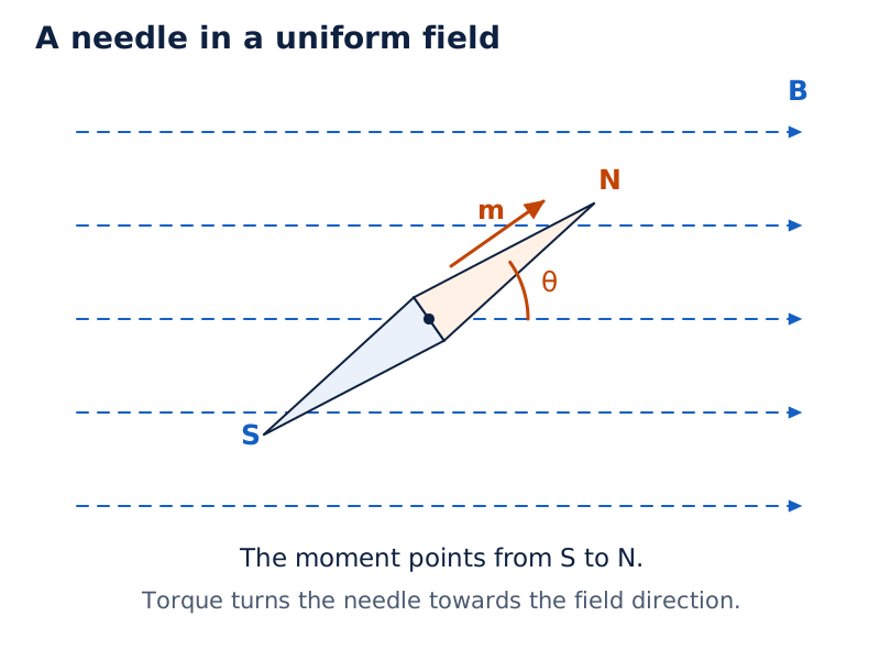
Parallel dashed arrows point right. The labelled north and south ends of the needle lie at an angle to these arrows, with the angle marked between the needle and the field direction.
Drawn by One Young India. See Fig. 5.3b in your NCERT textbook
Worked example 3. A short bar magnet at to a uniform field of experiences torque . Find its moment.
Formula: .
Substitute:
Answer: The moment is . The angle is between the moment and field, so the sine factor must be retained.
Why an iron nail can also be pulled
A nail near a bar magnet experiences a non-uniform field. The magnet induces a magnetic moment in the nail. Attraction on the nearer induced unlike pole exceeds the opposing effect on the more distant end, producing a resultant attractive force.
Worked example 4. A solenoid has turns, cross-sectional area , and current . It can turn horizontally in a uniform field of , at to its axis. Find moment, force and torque.
Formula: ; .
Substitute:
Answer: The moment is , net force is , and torque magnitude is . Uniformity of the field establishes the zero force.
How are magnetic potential energy and equilibrium related?
Derivation: Potential energy of a magnetic dipole
Let denote magnetic potential energy and an integration constant. For slow rotation at constant field, an external torque balances the magnetic restoring torque. Choose zero potential energy when moment and field are perpendicular.
- For the external torque magnitude needed to increase the angle,
- The change in potential energy for an infinitesimal angle change is
- Integrating while moment and field remain constant gives
- Applying the chosen reference gives
Result: Potential energy is lowest when the moment is parallel to the field and highest when it is antiparallel. The SI unit of potential energy is joule, .
Distinguishing stable and unstable equilibrium
At , the energy is , giving stable equilibrium. A small angular displacement produces a restoring tendency. At , the energy is , giving unstable equilibrium.
Both orientations have zero torque, so zero torque by itself cannot identify stability. The minimum or maximum character of the potential energy is essential. A perpendicular orientation has zero energy under the chosen reference, but its torque is not zero.
Worked example 5. A magnet of moment can rotate in a uniform field of . Find its energies in stable and unstable equilibrium.
Formula: .
Substitute:
Answer: Stable energy is ; unstable energy is . These correspond respectively to parallel and antiparallel orientations.
Let be the work done by an external torque during slow rotation, and let and be initial and final angles. With no change in kinetic energy, , where and are the corresponding potential energies.
Worked example 6. A moment of initially aligns with a uniform field of . Find the external work to turn it perpendicular and opposite to the field, and the torque at each final orientation.
Formula: ; .
Substitute:
Answer: Work is and , respectively. Torque is and zero. The subscripts identify the final angles in degrees; each rotation starts from the aligned position.
What does Gauss’s law for magnetism state?
Flux through a closed surface
Let be a small area vector normal to a surface element, directed outwards for a closed surface. Let denote magnetic flux through that element. The definition is .
Magnetic flux measures the field’s normal contribution over an area. The SI unit of magnetic flux is weber, , with . The vector area and dot product account for the orientation of the surface.
Definition: Gauss’s law for magnetism states that the net magnetic flux through any closed surface is zero. If denotes that closed surface, an infinitesimal outward area vector and the total flux, then .
One can divide the surface into small elements, calculate their fluxes and add them. In the limit of infinitesimal elements, this sum becomes the closed-surface integral. Field lines entering and leaving give cancelling contributions.
What the figure shows
Area vector and magnetic flux
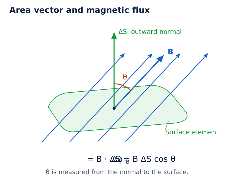
A small shaded surface element is crossed by parallel field lines. An upward normal arrow and a sloping field arrow form the marked angle, showing why surface orientation matters in calculating flux.
Drawn by One Young India. See Fig. 5.5 in your NCERT textbook
What zero net flux does not mean
Zero net flux does not mean that the field vanishes everywhere on the surface. It means the signed contributions cancel. A surface around one end of a bar magnet still has zero net magnetic flux because the field continues through the magnet.
For comparison, if is enclosed electric charge, electric flux obeys . Its value may therefore be non-zero. The magnetic result reflects the absence of isolated magnetic poles.
The word closed is essential. A surface patch can have non-zero magnetic flux. Gauss’s law refers to the complete boundary of a volume, not to one selected patch through which field lines pass.
How are magnetisation, intensity and permeability connected?
Separating the applied field from the material response
Let be magnetisation, the sample’s net magnetic moment and its volume. Magnetisation is defined by . The SI unit of magnetisation is ampere per metre, .
Let be turns per unit length of a long solenoid. Without a material core, its internal field magnitude is , where denotes the field produced by the winding current alone.
A core contributes a field . In this long-solenoid description, , and the total field is . The direction of magnetisation determines whether the core enhances or reduces the field.
The magnetic intensity is defined by . The SI unit of magnetic intensity is ampere per metre, . For the long solenoid, its magnitude is .
Derivation: Susceptibility and permeability
For a linear material, magnetic susceptibility relates magnetisation to intensity. Relative permeability compares material permeability with vacuum permeability. Both susceptibility and relative permeability are dimensionless.
- Start with the separation of applied and material contributions:
- For the linear response, substitute the definition of susceptibility:
- Introduce permeability through the constitutive relation:
- Comparing the coefficients gives
Result: Knowing susceptibility, relative permeability or permeability determines the other two. These simple proportional relations describe a linear response; one should not assume an unrestricted constant susceptibility for every magnetic material under all conditions.
Worked example 7. A long solenoid has turns per unit length, current , and a core with . Find intensity, magnetisation and total field. Use .
Formula: ; ; .
Substitute:
Answer: Intensity is , magnetisation is , and field is approximately . The unrounded field is retained before the final rounding.
How do diamagnetic and paramagnetic materials differ?
Diamagnetism: an opposing response
Diamagnetic substances develop magnetisation opposite to an applied field. They tend to move from stronger to weaker regions of a non-uniform field. Their susceptibility is negative, and their relative permeability is below unity.
In the simple atomic description, the resultant moment of an atom is initially zero. An applied field changes the orbital motion of electrons, inducing a net moment opposite to the applied field. The resulting magnetic response weakens the field inside the substance.
Examples include bismuth, copper, lead, silicon, water and sodium chloride, as well as nitrogen at standard temperature and pressure. Diamagnetism is present in all substances, but other magnetic effects can conceal its usually weak contribution.
Paramagnetism: partial alignment of permanent moments
Paramagnetic substances have atoms, ions or molecules with permanent magnetic dipole moments. Random thermal motion prevents these moments from producing net magnetisation in the absence of an applied field. The material can therefore have microscopic moments without a macroscopic magnetic moment.
An applied field favours alignment of these moments with itself. The material becomes weakly magnetised along the field and tends to move from a weaker to a stronger field region. Its susceptibility is small and positive, and its relative permeability is slightly above unity.
Examples include aluminium, sodium, calcium and copper chloride, together with oxygen at standard temperature and pressure. Increasing the field or lowering temperature increases magnetisation until saturation is reached, when the dipoles are fully aligned.
What the figure shows
Diamagnetic and paramagnetic responses
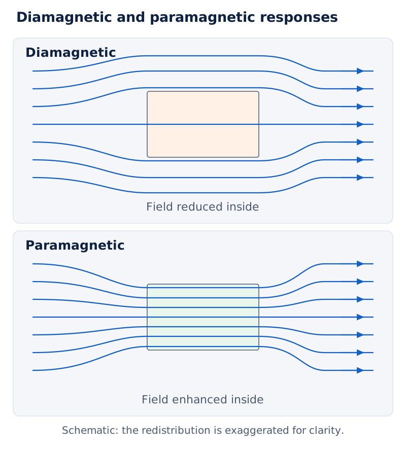
In panel (a), field lines bend away from a shaded block and are less concentrated inside. In panel (b), the lines bend into a shaded block and become more concentrated within it.
Drawn by One Young India. See Fig. 5.7 in your NCERT textbook
| Property | Diamagnetic | Paramagnetic |
|---|---|---|
| Susceptibility | Negative | Small and positive |
| Magnetisation direction | Opposite to applied field | Along applied field |
| Field inside sample | Reduced | Enhanced slightly |
| Motion in non-uniform field | Towards weaker field | Towards stronger field |
| Atomic starting point | No resultant atomic moment in the simple description | Permanent moments with random orientations |
Perfect diamagnetism
A superconductor exhibits perfect diamagnetism in the state described here: magnetic field is expelled from its interior. This is the Meissner effect. The associated values are , , and .
Perfect diamagnetism must not be confused with the small reduction of internal field in an ordinary diamagnetic material. Superconductors also exhibit perfect conductivity, but the two properties are distinct aspects of their behaviour.
Why are ferromagnets strongly magnetised?
Domains and cooperative alignment
Ferromagnetic substances become strongly magnetised in an applied field and are strongly attracted towards stronger field regions. Their large response differs from the weak attraction of a paramagnet. Iron, cobalt, nickel and gadolinium are examples.
The atoms possess magnetic moments, but an additional cooperative interaction causes neighbouring moments to align spontaneously over a macroscopic region called a domain. Each domain has a net magnetisation even when the specimen as a whole is unmagnetised.
In an initially unmagnetised sample, the directions of magnetisation vary between domains, giving no bulk magnetisation. Applying a field causes domains to orient towards the field, while domains already favourably oriented grow in size. The resulting bulk magnetisation can be very large.
What the figure shows
Random and aligned domains
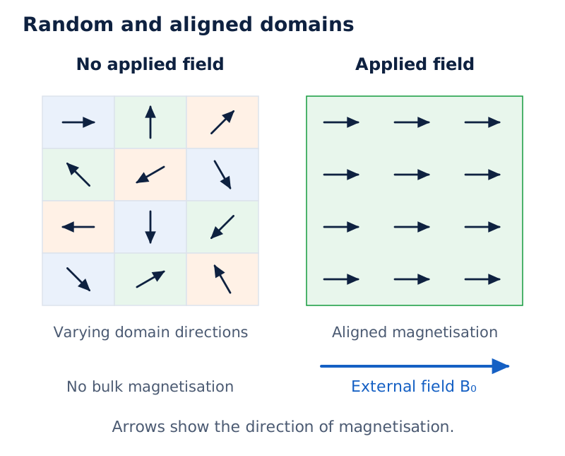
Panel (a) contains many regions with arrows pointing in different directions. Panel (b) shows arrows aligned to the right, matching the external field arrow drawn beneath the sample.
Drawn by One Young India. See Fig. 5.8 in your NCERT textbook
Hard and soft magnetic materials
In hard ferromagnets, magnetisation persists after the external field is removed. Such materials can form permanent magnets, including compass needles. Alnico and naturally occurring lodestone are examples. Alnico contains iron, aluminium, nickel, cobalt and copper.
In soft ferromagnetic materials, magnetisation disappears on removing the external field in the idealised description. Soft iron is an example. The distinction concerns retention of magnetisation, rather than whether either material responds to an applied field.
| Material class | Magnetic response | Permeability comparison |
|---|---|---|
| Diamagnetic | Opposes the applied field | |
| Paramagnetic | Weakly reinforces the applied field | , slightly |
| Ferromagnetic | Strongly reinforces the applied field |
Temperature and loss of ferromagnetism
Ferromagnetic behaviour depends on temperature. At sufficiently high temperature, the domain structure disintegrates and the material becomes paramagnetic. Thus, a material’s magnetic classification must be understood together with the physical conditions under which its behaviour is observed.
The microscopic distinction is important: paramagnetism involves alignment of individual permanent moments against random thermal motion, whereas ferromagnetism involves cooperative alignment within domains. This explains why merely knowing that atoms have magnetic moments does not identify the strength of the bulk response.
Glossary
- Magnetic dipole — A basic magnetic element represented by a bar magnet or current loop, possessing a magnetic moment.
- Magnetic field line — A curve whose tangent gives the direction of the net magnetic field at each point.
- Magnetic moment — A vector characterising a magnetic dipole and determining its torque in an external magnetic field.
- Magnetic flux — The surface contribution obtained by combining magnetic field with oriented area through a dot product.
- Magnetisation — The net magnetic dipole moment per unit volume of a material sample.
- Magnetic intensity — A vector field separating the externally imposed magnetic contribution from the magnetisation of the material.
- Magnetic susceptibility — A dimensionless measure relating magnetisation to magnetic intensity for a material with linear response.
- Relative permeability — The dimensionless ratio of a material’s magnetic permeability to the permeability of free space.
- Diamagnetism — A magnetic response in which induced magnetisation opposes the applied field and the substance is repelled.
- Paramagnetism — Weak magnetisation along an applied field through preferential alignment of permanent atomic or molecular magnetic moments.
- Ferromagnetism — Strong magnetic behaviour associated with cooperative alignment of atomic moments within magnetised regions called domains.
- Magnetic domain — A region of a ferromagnetic material in which atomic magnetic moments spontaneously align in a common direction.
- Meissner effect — The expulsion of magnetic field from a superconductor, expressing its property of perfect diamagnetism.
Common errors and misconceptions
- Misconception: Cutting a bar magnet separates its poles. Correct: Each resulting piece is a magnet with both north and south poles.
- Misconception: Magnetic field lines end at the south pole. Correct: They continue through the magnet and form closed loops.
- Misconception: Field lines give the force direction on any moving charge. Correct: The non-zero magnetic force is perpendicular to the magnetic field.
- Misconception: Zero torque proves stable equilibrium. Correct: Both parallel and antiparallel orientations have zero torque, but only the parallel orientation minimises potential energy.
- Misconception: Zero flux through a closed surface means zero field there. Correct: Non-zero inward and outward flux contributions can cancel.
- Misconception: Magnetisation and magnetic intensity have units of tesla. Correct: Both use ; magnetic field uses tesla.
- Misconception: Every ferromagnet retains magnetisation after field removal. Correct: Hard ferromagnets retain it, while soft ferromagnets lose it in the idealised description.
- Misconception: The equatorial field points along the magnetic moment. Correct: It points opposite to the moment; the axial field points along it.
Exam-style questions with model answers
Q1. State Gauss’s law for magnetism and explain its relation to magnetic poles. [2 marks]
- The net magnetic flux through any closed surface is zero: .
- Magnetic field lines are continuous, with no isolated magnetic poles acting as sources or sinks. Inward and outward contributions therefore cancel.
Q2. A short magnet at to a uniform field experiences torque . Calculate its moment. [2 marks]
- Use , where torque, magnetic moment, field and their angle are represented by the stated symbols.
- Substitution gives This is the magnitude of the magnetic moment.
Q3. Compare diamagnetic and paramagnetic materials in terms of microscopic moments, susceptibility and motion in a non-uniform field. Give one example of each. [3 marks]
- In the simple description, a diamagnetic atom initially has zero resultant magnetic moment. An applied field induces a moment opposite to itself. A paramagnetic atom or molecule already has a permanent moment, with thermal motion producing random orientations without an applied field.
- Diamagnetic susceptibility is negative; paramagnetic susceptibility is small and positive.
- Diamagnetic materials move towards weaker fields, whereas paramagnetic materials move towards stronger fields. Bismuth is diamagnetic and aluminium is paramagnetic.
Q4. Derive the magnetic potential energy of a dipole in a uniform field, choosing zero energy when it is perpendicular to the field. Identify stable and unstable equilibrium. [5 marks]
- Let be the magnetic moment magnitude, the uniform field magnitude, their angle and the potential energy. For slow rotation, the applied torque balances the restoring torque: .
- The infinitesimal external work raises potential energy: . The moment and field magnitudes remain constant throughout the rotation.
- Integration gives , where is the integration constant. The specified reference gives .
- Thus . Parallel alignment gives the minimum and stable equilibrium; antiparallel alignment gives the maximum and unstable equilibrium.
- Both equilibrium orientations have zero torque. Their different energy behaviour explains why zero torque alone is insufficient to determine stability.
Q5. A long solenoid has turns per unit length, current , and a core of relative permeability . Calculate magnetic intensity, magnetisation and field. Use . [4 marks]
- The applied winding determines magnetic intensity: . Here is turns per unit length and is current.
- Susceptibility is , where is relative permeability. Therefore .
- The total field is Rounded appropriately, the field is . Magnetisation describes the core’s response, while intensity describes the applied winding contribution.
Q6. Explain ferromagnetic domains, magnetisation in an applied field, hard and soft ferromagnets, and the effect of sufficiently high temperature. [5 marks]
- Atomic magnetic moments in a ferromagnet interact cooperatively and align in a common direction within a domain. Each domain consequently has its own net magnetisation.
- An unmagnetised specimen can contain such magnetised domains because their directions vary across the specimen, producing no bulk magnetisation.
- An applied field changes domain orientations and allows favourably oriented domains to grow. The resulting strong net magnetisation explains the large response and attraction towards stronger field regions.
- Hard ferromagnets, such as alnico, retain magnetisation after field removal and can form permanent magnets. Soft ferromagnets, such as soft iron, lose magnetisation in the idealised description.
- At sufficiently high temperature, the domain structure disintegrates and ferromagnetic behaviour changes to paramagnetic behaviour. Temperature therefore affects whether the strong cooperative response persists.
Q7. A short magnet of moment produces fields at axial and equatorial points from its centre. Calculate their magnitudes and state directions. Assume the dipole approximation and use . [3 marks]
- For the axial point, This field points parallel to the magnetic moment.
- For the equatorial point, Its direction is opposite to the magnetic moment.
- The axial magnitude is twice the equatorial magnitude at equal distance. The negative sign in the equatorial vector expression represents direction, not a negative field magnitude. Both calculations require distance large compared with magnet size, as assumed.
Key takeaways
- A bar magnet retains both poles when divided; its field pattern resembles that of a current-carrying solenoid.
- Magnetic field lines form continuous loops, and their tangent gives field direction rather than magnetic force direction.
- In a uniform field, a dipole experiences zero net force but generally experiences a torque tending to align it.
- Parallel alignment minimises magnetic potential energy, whereas antiparallel alignment maximises it despite also having zero torque.
- Gauss’s law gives zero magnetic flux through every closed surface without requiring zero magnetic field on that surface.
- Magnetisation describes net moment per volume; magnetic intensity separates the applied contribution from the material response.
- Diamagnetic materials oppose the applied field, while paramagnetic and ferromagnetic materials reinforce it with different response strengths.
- Ferromagnetic domains explain strong magnetisation; retention after field removal distinguishes hard magnetic materials from soft magnetic materials.
Test yourself
Why can magnetic field lines not intersect?
An intersection would give two different directions for the net magnetic field at the same point.
Does a magnet in a uniform field necessarily experience a net force?
No. Its net force is zero, although a torque can rotate it unless its moment is parallel or antiparallel to the field.
Which way does the equatorial field of a short magnet point?
It points opposite to the magnetic moment, provided the observation point is sufficiently far from the magnet.
Why can an unmagnetised ferromagnet still contain magnetised domains?
Different domains have different magnetisation directions, so their contributions can cancel in the bulk sample.
What are the units of magnetisation and magnetic intensity?
Both have SI unit ampere per metre, , although they describe different contributions to magnetic behaviour.
What distinguishes perfect diamagnetism from ordinary diamagnetism?
Perfect diamagnetism expels the internal magnetic field in the superconducting state; ordinary diamagnetism usually causes only a slight reduction.
Why does lowering temperature favour paramagnetic magnetisation?
Reduced thermal disturbance favours alignment of permanent magnetic moments with the applied field, increasing magnetisation towards saturation.
Why is the antiparallel orientation unstable even though its torque is zero?
Its potential energy is a maximum, so a small angular displacement tends to move the dipole away from that orientation.