
Moving Charges and Magnetism | CBSE Class 12 Physics Notes
On this page
Watch & explore
Start with a few high-quality watches, then dive into the notes below.

Learnacy Labs Try it hands-on: open the Magnetism lab
This note covers magnetic fields and forces, motion of charged particles, the Biot-Savart law, circular current loops, Ampere’s circuital law, solenoids, forces between parallel currents, magnetic dipoles, torque on current loops, moving coil galvanometers, and their conversion into ammeters and voltmeters.
How are moving charges and magnetic fields connected?
Moving charges produce magnetic fields. Oersted observed that a compass needle near a current-carrying straight wire changes direction. Reversing the current reverses the needle’s orientation. Increasing the current or bringing the needle nearer increases the deflection, provided the wire’s field dominates the earth’s field.
The needles align tangentially to circles centred on the wire. Iron filings also arrange themselves in concentric circles. These observations connect electric current with magnetism and show that the field surrounding a straight wire has a definite direction.
What the figure shows
Compass needles around a straight wire
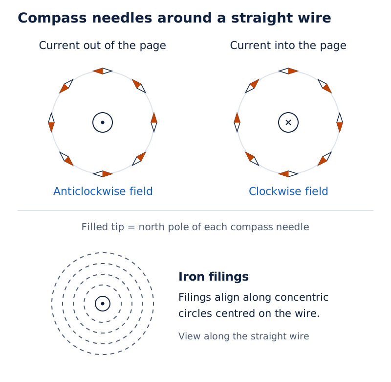
Two rings of compass needles surround a central dot or cross, showing reversed orientations. A third drawing shows iron filings arranged in concentric circles around the wire.
Drawn by One Young India. See Fig. 4.1 in your NCERT textbook
What do field symbols and directions mean?
The magnetic field, written as the vector , specifies magnetic influence at a point. A dot represents a direction out of the page; a cross represents a direction into the page. Fields from several sources add vectorially by the principle of superposition.
Let be a particle’s signed charge, its velocity, the electric field, and the total electromagnetic force. The Lorentz force is
Here the cross denotes a vector product. The magnetic part, , has magnitude ; is speed and is field magnitude. If is the angle between velocity and magnetic field, then
The force is perpendicular to both vectors. Use the right-hand cross-product rule for positive charge, then reverse the direction for negative charge. The magnetic force vanishes for a stationary particle or motion parallel or antiparallel to the field.
How is magnetic field strength measured?
The SI unit of magnetic field is the tesla, symbol . A field of one tesla produces one newton on one coulomb moving perpendicularly at one metre per second:
The non-SI gauss satisfies . In the steady-current treatment, fields do not change with time. Unit symbols distinguish tesla from the period used below. The SI unit of electric charge is the coulomb, symbol ; the SI unit of current is the ampere, symbol .
Why does a current-carrying conductor experience a magnetic force?
A current-carrying wire contains moving charge carriers. An external magnetic field acts on these charges, so the conductor experiences a force. The field used in the force formula is the external field, rather than the field generated by the wire itself.
Let be the steady current and a vector whose magnitude is the straight wire’s length and whose direction follows conventional current. In a uniform magnetic field,
where now measures the angle between conventional current and the field. Current is a scalar; the length vector supplies the direction. The SI unit of force is the newton, symbol .
Derivation: Force on a straight current-carrying rod
Let be the number of mobile carriers per unit volume, the cross-sectional area, the signed charge per carrier, the drift velocity, and the current density.
- The volume of the rod is , so its number of mobile carriers is .
- The magnetic forces add to give .
- Use the current-density relation , giving .
- For uniform current density, . Transferring the current direction to the length vector gives .
Result: The rod’s force depends on current, length, field and orientation. For a curved wire, divide it into short vector elements and add their forces, using the external field at each element.
Worked example 1. A wire of mass , length , and current is suspended by a horizontal field perpendicular to it. Find the field, taking gravitational acceleration .
Formula: Let be the wire’s mass. Balance requires , so .
Answer:
- Convert the mass: .
- Substitute:
- Evaluate: . Choose its direction so the magnetic force is upward.
How does a charged particle move in a uniform magnetic field?
A magnetic force does no work on a moving particle because it is perpendicular to the instantaneous velocity. Its direction of motion can change while its speed and kinetic energy remain constant. This statement concerns the magnetic force alone; an electric field can transfer energy.
When the initial velocity is perpendicular to a uniform field, the magnetic force provides the centripetal force. When the velocity has both perpendicular and parallel components, the particle follows a helix. Its parallel component remains unchanged, while its perpendicular component produces circular motion.
Derivation: Radius, frequency and pitch
Let be particle mass, the orbit radius, and the perpendicular and parallel velocity components, the angular frequency, the frequency, the period, and the pitch.
- Equate the centripetal and magnetic force magnitudes: .
- Cancel the nonzero perpendicular speed to obtain .
- Use , giving and .
- The period is . The advance along the field in one period is .
Result: For a fixed field and particle mass, the cyclotron frequency does not depend on speed or radius in this treatment. The charge sign changes the sense of rotation; the absolute charge gives positive radius and frequency.
What the figure shows
Circular and helical motion
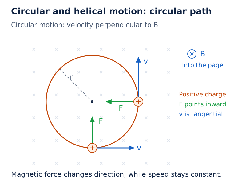
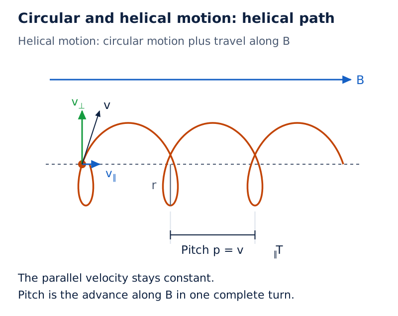
The circular-path drawing shows positive charges, tangential velocity arrows and inward force arrows in a field represented by crosses. The helix drawing labels parallel and perpendicular velocity components, pitch, radius and the axial magnetic field.
Drawn by One Young India. See Figs. 4.5 and 4.6 in your NCERT textbook
Worked example 2. An electron has mass , charge magnitude , and speed . It enters a perpendicular field of . Find its radius, frequency and kinetic energy. Use .
Formula: , , and , where is kinetic energy.
Answer:
- Radius:
- Frequency:
- Energy:
- Convert:
What does the Biot-Savart law tell us about a current element?
The Biot-Savart law gives the magnetic field contribution from a small current element. It applies here to steady currents in vacuum. Let be a directed length element along the current, and the displacement from that element to the observation point.
Write for the displacement magnitude and for the element’s field contribution. The constant is the permeability of free space. Then
If is the angle between the length element and displacement vector, the magnitude is
How are magnitude and direction determined?
The contribution is proportional to current and element length, and inversely proportional to the square of the separation. Its direction is perpendicular to the plane containing the two vectors. The right-hand cross-product rule fixes the sense. An observation point along the element’s line receives zero contribution from that element.
The SI unit of permeability of free space is tesla metre per ampere, . For the calculations here, use . Obtain a complete conductor’s field by integrating its vector contributions, rather than adding their magnitudes indiscriminately.
How does this compare with the electrostatic field law?
| Feature | Electrostatic field of a point charge | Magnetic field of a current element |
|---|---|---|
| Source | A scalar electric charge | A directed current element |
| Distance dependence | Inverse square for a point source | Inverse square for an element |
| Direction | Along the source-to-point line | Perpendicular to the element-displacement plane |
| Angular factor | No corresponding element-angle factor | Includes the sine of the element-displacement angle |
| Several sources | Fields add vectorially | Fields add vectorially |
Note: The inverse-square dependence belongs to an individual current element. Integrating over a complete wire or coil can produce a different distance dependence because the geometry and directions also matter.
How is the field on the axis of a circular current loop derived?
Consider a circular current loop in vacuum carrying steady current . Let be its radius and the axial distance of an observation point from the centre. Every element is the same distance from that point, making the geometry particularly useful.
The field of each element has axial and transverse components. Symmetry makes the transverse contributions from diametrically opposite elements cancel. Their axial components point in the same direction and add. This cancellation must precede the final scalar integration.
Derivation: Axial field of a circular loop
- The element-to-point distance obeys . Since the element is perpendicular to this displacement, .
- Let be the angle between the element’s field and the axis. Geometry gives .
- The axial contribution is , where denotes that component.
- Integrate around the circumference, , obtaining .
- At the centre, , so . For closely wound turns, where is the number of turns, .
Result: Curl the right-hand fingers in the current direction; the thumb indicates the axial field direction. For closely wound turns of the same radius, their centre fields add directly.
What the figure shows
Components of a loop’s magnetic field
The drawing shows a loop centred at the origin, an observation point on its horizontal axis, an element-to-point displacement, and field components parallel and perpendicular to that axis.
See Fig. 4.9 in your NCERT textbook
Worked example 3. A tightly wound coil has turns of radius and carries . Find the field at its centre using .
Formula: .
Answer:
- Convert radius: .
- Substitute:
- Evaluate: .
How does Ampere’s circuital law simplify magnetic-field calculations?
Ampere’s circuital law relates magnetic-field circulation around a closed path to the net current passing through a surface bounded by that path. For steady currents, let denote this signed enclosed current. The law is
The circle on the integral denotes a closed path. The dot product selects the field component along each path element. Curl the right-hand fingers in the chosen direction of traversal; the thumb indicates the direction counted as positive current through the surface.
Derivation: Field outside a long straight wire
- Choose a circular Amperian loop of radius , centred on a long straight wire carrying current .
- Cylindrical symmetry makes the field tangential and constant in magnitude around the loop. Therefore .
- The loop encloses the entire current: . Hence .
- Solving gives . The field direction follows the curled fingers when the right thumb points along the current.
Result: Outside the wire, the field decreases inversely with radial distance. Ampere’s law holds for any closed loop in this steady-current treatment, but convenient evaluation requires sufficient symmetry.
What changes inside a wire of finite radius?
Let be the wire radius, with total current uniformly distributed across its circular cross-section. An interior loop encloses only the corresponding fraction of current. The numbered steps are:
- For , the enclosed fraction is .
- Substitution gives .
- Thus inside. Outside, .
The interior field increases linearly from zero at the axis. The exterior field decreases with distance. Uniform current density is essential to the interior expression; do not use the full current for every interior loop.
Why is the field inside a long solenoid nearly uniform?
A solenoid is a wire wound into a helix with closely spaced turns. Insulation prevents neighbouring turns from making electrical contact. Its field is the vector sum of the fields produced by individual turns. A long solenoid has a length much greater than its radius.
Near the middle of a finite solenoid, the interior field is strong and approximately uniform. The exterior field is weaker. In the ideal long-solenoid approximation, the outside field is neglected and the inside field is parallel to the axis.
Derivation: Magnetic field of a long solenoid
Here denotes turns per unit length, is the current in every turn, and is the length of an axial side of a rectangular Amperian loop.
- Choose a rectangle with one axial side inside the solenoid and its opposite side outside. The interior contribution is .
- The exterior field is taken as zero. The transverse sides have zero dot product with the axial field, giving .
- The loop encloses turns, each carrying current . Thus .
- Ampere’s law gives , and cancellation of yields .
Result: The field increases with current and turns per unit length. This expression describes the ideal long solenoid in vacuum; end effects prevent the same uniform-field approximation from applying everywhere to a finite solenoid.
What the figure shows
Finite and long solenoids
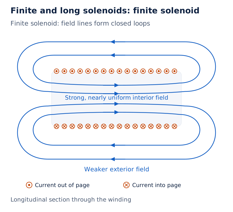
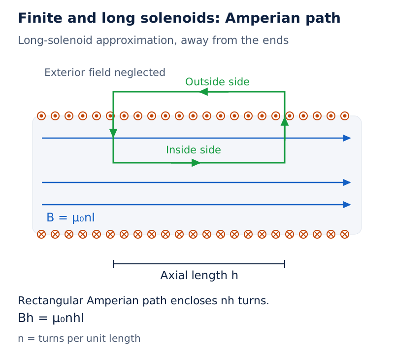
Field lines run through the interior and curve around outside the finite solenoid. The long-solenoid drawing adds a rectangular path with one long side inside and the other outside, and marks the axial length used in the calculation.
Drawn by One Young India. See Figs. 4.15 and 4.16 in your NCERT textbook
Worked example 4. A solenoid of length , radius , and turns carries . Estimate its interior field using .
Formula: and , where is solenoid length and its total number of turns.
Answer:
- The radius is , so the length-to-radius ratio is , supporting the long-solenoid approximation.
- The turn density is .
- Substitute:
Why do parallel currents attract while opposite currents repel?
Each current-carrying wire produces a magnetic field that acts on the other wire. The force therefore follows by combining the field of a long straight wire with the force on a conductor in an external field. The two laws describe successive parts of the same interaction.
Derivation: Force between two long parallel wires
Let and be the current magnitudes in wires labelled a and b, their separation, the length considered, and the field of wire a at wire b.
- The first wire produces at the second wire.
- This field is perpendicular to the second wire. Its force magnitude is .
- Substitute to obtain .
- Writing for force per unit length gives .
Result: Right-hand rules show that currents in the same direction attract, while currents in opposite directions repel. The forces on equal lengths are equal and opposite. This result assumes long straight parallel wires and steady currents.
Worked example 5. Two long parallel wires carry and in the same direction. Their separation is . Find the force on a section, using .
Formula: .
Answer:
- Convert lengths: and .
- Substitute:
- The force acts towards the other wire because the currents are parallel.
What was the historical force-based definition of the ampere?
The definition adopted in 1946 used equal steady currents in two very long parallel conductors of negligible cross-section, one metre apart in vacuum. A current of one ampere in each produced on each conductor. This is the historical force-based definition.
How does a magnetic field exert torque on a current loop?
A closed current loop in a uniform magnetic field has zero net force, yet it can experience a turning effect. Equal and opposite forces may act along different lines, forming a couple. Zero resultant force therefore does not imply zero torque.
Let and be the sides of a rectangular loop, and its area. Take the sides of length perpendicular to the field. The angle is measured between the loop’s normal and the field, not between its plane and the field.
Derivation: Torque on a rectangular loop
- For the opposite sides of length perpendicular to the field, each force has magnitude . The forces are equal and opposite.
- The perpendicular separation of their lines of action is .
- The torque magnitude, denoted by , is .
- For identical turns, the torques add: .
Result: Torque is greatest when the loop’s normal is perpendicular to the field, meaning the field lies in the loop’s plane. It vanishes when the normal is parallel or antiparallel to the field.
How does magnetic moment describe the loop?
The magnetic moment is , where is the area vector normal to the loop. Here denotes magnetic moment, rather than the mass symbol used earlier. Curl the fingers along the current to find its direction with the thumb.
The SI unit of magnetic moment is ampere square metre, . The torque relation is . Parallel alignment is stable: a small displacement produces a restoring torque. Antiparallel alignment is unstable, even though the torque at exact opposition is zero.
Worked example 6. A square coil of side has turns and carries . Its normal makes with a uniform field of . Find the torque.
Formula: and , with now the square’s side.
Answer:
- Convert and square: , so .
- Substitute:
- The stated angle is already measured from the normal, so no complementary-angle conversion is required.
Why can a small current loop be treated as a magnetic dipole?
A current loop both produces a magnetic field and experiences torque in an external magnetic field. At distances much larger than its size, its field resembles that of a magnetic dipole. This connects a microscopic current loop with the behaviour of a magnetic needle.
Derivation: Distant axial field
For a single circular loop, let be the magnitude of its magnetic moment, its radius and the positive distance along its axis.
- Start with the loop field: .
- At distances satisfying , neglect beside , giving .
- Use and to obtain .
Result: The distant axial field decreases as the inverse cube of distance. In the plane of the loop, at the same large distance, the field magnitude is , half the axial magnitude.
The dipole description extends to other planar current loops through their current and area vector. It is a large-distance approximation for a finite loop, so it should not replace the exact axial expression close to that loop.
There is also a fundamental difference from an electric dipole: separated electric charges are known, whereas isolated magnetic monopoles have not been observed. Circulating currents explain much magnetic behaviour, but electrons and protons also possess intrinsic magnetic moments not accounted for by such circulating currents.
How does a moving coil galvanometer detect and measure current?
A moving coil galvanometer uses magnetic torque to produce a visible deflection. It contains a many-turn coil that rotates about a fixed axis, a magnetic field, a soft iron core, a spring, and a pointer moving over a scale.
The cylindrical soft iron core strengthens the field and helps make it radial. This geometry keeps the magnetic torque proportional to current throughout the working deflection, without introducing a changing sine factor. The spring opposes the turning effect and establishes an equilibrium position.
Derivation: Deflection and current sensitivity
Let be the coil’s angular deflection and the spring’s torsional constant, or restoring torque per unit twist. The SI unit of torsional constant is newton metre per radian, .
- In the radial field, the magnetic torque is .
- The spring supplies an opposing torque of magnitude . At equilibrium, .
- Rearranging gives . Deflection is proportional to current for a fixed instrument.
- Define current sensitivity as deflection per unit current. Then .
Result: A larger deflection for a given current means greater current sensitivity. Increasing the number of turns is one way to increase it. The instrument’s sensitivity must suit the current being measured.
What the figure shows
Moving coil galvanometer
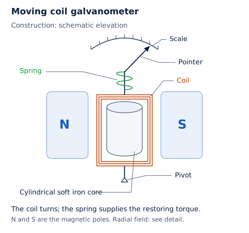
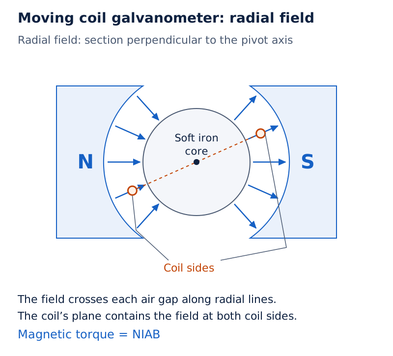
The drawing labels the coil between magnetic poles, cylindrical soft iron core, pivot, spring, pointer and scale. The magnetic-field region is identified as radial.
Drawn by One Young India. See Fig. 4.20 in your NCERT textbook
Why does the scale sometimes have a central zero?
For use as a current detector, the zero can be placed at the scale’s centre. Opposite current directions then produce opposite deflections. A galvanometer used this way indicates whether current flows and its direction, as in a bridge arrangement.
A sensitive galvanometer cannot simply replace an ordinary ammeter: it reaches full-scale deflection at small currents, and its resistance can appreciably change the circuit current. Additional resistance arrangements adapt it for current or voltage measurement.
How is a galvanometer converted into an ammeter or voltmeter?
An ammeter measures current through a circuit branch and is connected in series with that branch. Its resistance should be small enough to cause little change in current. A low-resistance shunt connected across the galvanometer carries most of the total current.
A voltmeter measures potential difference and is connected across the relevant circuit section. A large resistance in series with its galvanometer coil limits the current drawn. Distinguish the internal series resistor from the instrument’s parallel connection to the measured circuit.
How do the conversion resistances follow from circuit laws?
Let be galvanometer resistance, its full-scale current, shunt resistance, the desired ammeter range, the added series resistance, and the desired voltmeter range.
- The parallel branches of an ammeter have equal voltage: .
- Solving gives . Its equivalent resistance is , where denotes ammeter resistance.
- For the voltmeter, the same current flows through both series resistances: .
- Hence , and the total voltmeter resistance is , where denotes that total resistance.
When the shunt resistance is much smaller than coil resistance, . When the added series resistance is much larger than coil resistance, . These approximations explain why the ammeter has low resistance and the voltmeter high resistance.
Does greater current sensitivity guarantee greater voltage sensitivity?
Define voltage sensitivity as deflection per unit voltage. For total instrument resistance , . Doubling the number of turns doubles current sensitivity if the other factors remain constant.
However, extra wire can also double resistance. If turns and total resistance both double, voltage sensitivity remains unchanged. Thus current sensitivity and voltage sensitivity must be considered separately.
| Feature | Ammeter | Voltmeter |
|---|---|---|
| Circuit connection | In series with the measured branch | In parallel across the measured section |
| Conversion component | Small resistance across the coil | Large resistance in series with the coil |
| Desired instrument resistance | Very low | Very high |
| Purpose of conversion | Divert most current away from the coil | Limit current drawn from the measured section |
Worked example 7. A source drives a resistor in series with a measuring instrument. Compare the current for a galvanometer, that galvanometer shunted by , and an ideal zero-resistance ammeter. Neglect source internal resistance.
Formula: , where is total circuit resistance, and .
Answer:
- With the galvanometer alone,
- The shunted instrument has resistance
- The resulting current is
- For the ideal ammeter,
The shunt brings the measured-circuit current close to its undisturbed value. Connecting the galvanometer alone would greatly reduce that current. This illustrates why instrument resistance is part of the measurement problem, rather than an incidental construction detail.
Glossary
- Magnetic field — A vector field associated with moving charges and magnetic moments, capable of exerting forces on moving charges.
- Lorentz force — The total force on a charged particle arising from the electric and magnetic fields present.
- Superposition — The rule that magnetic fields from several sources combine by vector addition at an observation point.
- Tesla — The SI magnetic-field unit corresponding to one newton on one coulomb moving perpendicularly at one metre per second.
- Pitch — The distance travelled along the magnetic-field direction during one complete revolution of a helical trajectory.
- Cyclotron frequency — The frequency of circular motion of a charged particle in a uniform magnetic field.
- Current element — A directed infinitesimal conductor segment multiplied by its current, used to calculate a magnetic-field contribution.
- Amperian loop — A chosen closed integration path used to relate magnetic-field circulation to enclosed steady current.
- Solenoid — A wire wound into closely spaced helical turns, producing an approximately uniform interior field when sufficiently long.
- Magnetic moment — A vector describing a current loop’s magnetic strength and orientation, directed normally by the right-hand rule.
- Radial magnetic field — A field arrangement in a moving coil galvanometer that maintains the full magnetic turning effect throughout deflection.
- Shunt — A small resistance connected in parallel with a galvanometer to carry most of an ammeter’s current.
- Current sensitivity — The angular deflection per unit current through a galvanometer, determined by its coil, field and spring.
Common errors and misconceptions
- Misconception: Every charged particle in a magnetic field experiences force. Correct: A stationary charge has no magnetic force; motion parallel or antiparallel to the field also gives zero magnetic force.
- Misconception: A magnetic field increases a particle’s speed as it bends the path. Correct: The magnetic force is perpendicular to velocity, so it changes direction without doing work.
- Misconception: A negative charge follows the positive-charge force direction. Correct: Determine the velocity-field cross product first, then reverse its direction for negative charge.
- Misconception: Ampere’s law always permits taking the field outside the integral. Correct: The law holds for steady currents, but that simplification requires appropriate symmetry and field behaviour along the chosen path.
- Misconception: Like currents repel because like charges repel. Correct: Parallel currents in the same direction attract, whereas currents in opposite directions repel.
- Misconception: The angle in the loop-torque formula is measured from the coil’s plane. Correct: It is measured from the area vector, which is normal to that plane.
- Misconception: Zero torque guarantees stable equilibrium. Correct: Magnetic moment parallel to the field gives stable equilibrium; antiparallel alignment gives unstable equilibrium.
- Misconception: Adding more turns must increase voltage sensitivity. Correct: More turns can increase both current sensitivity and resistance, leaving voltage sensitivity unchanged.
Exam-style questions with model answers
Q1. Why does a magnetic force do no work on a moving charged particle? Can its momentum change? [2 marks]
- The magnetic force is perpendicular to instantaneous velocity, so it has no component along the displacement and does no work.
- The particle’s speed stays unchanged under this force alone, but its momentum direction can change as its path bends.
Q2. A particle moves along the positive -axis in a magnetic field along the positive -axis. With no electric field, give the force directions for an electron and a proton. [2 marks]
- The cross product points along the positive -axis, perpendicular to the velocity and field.
- The proton’s positive charge gives force along positive ; the electron’s negative charge reverses it to negative .
Q3. A particle of mass , charge , and speed moves perpendicular to a uniform magnetic field of magnitude , with no other force. Derive its orbit radius and frequency. [3 marks]
- The magnetic force has magnitude , remains perpendicular to motion, and supplies the centripetal force. The speed stays constant because this force does no work.
- Equating force magnitudes gives , hence the radius is .
- One revolution covers the circumference, so the frequency is . Thus it is independent of speed for a fixed particle and field in this treatment.
Q4. A long straight wire carries . Calculate the magnetic-field magnitude at a point from it. Use . State the field direction relative to a circle centred on the wire. [3 marks]
- Use the long-wire expression , where is current and the perpendicular distance from the wire. Convert the distance: .
- Substitute with units:
- The field is tangential to the circle through the point. Its sense is given by curled right-hand fingers when the thumb points along the current.
Q5. Derive the magnetic field on the axis of a circular loop of radius , carrying steady current in vacuum, at axial distance . Hence state the field at its centre. Use for vacuum permeability. [5 marks]
- Every element is at distance from the observation point. The directed element is perpendicular to its displacement towards that point, so the Biot-Savart magnitude is .
- Resolve the contribution into axial and transverse components. Transverse components of diametrically opposite elements cancel by symmetry, leaving only the axial contributions to add.
- The axial projection factor is . Thus .
- Integrate over the full circumference, using , to obtain .
- At the centre, , yielding . The field is along the axis, with its sense fixed by the right-hand rule applied to the current.
Q6. A rectangular coil has turns, side lengths and , and current . Its normal makes angle with a uniform magnetic field , and the sides of length are perpendicular to the field. Derive its torque and distinguish stable from unstable equilibrium. [5 marks]
- The forces on opposite sides are equal and opposite, so the closed coil has zero resultant force. Nevertheless, a pair of non-collinear forces can produce a turning effect.
- For the sides of length perpendicular to the field, each force is . Their perpendicular separation is , where the given angle is measured from the coil’s normal.
- For one turn, . With area , adding all turns gives .
- Define magnetic moment , where the area vector follows the right-hand rule. Then .
- Parallel moment and field give stable equilibrium because a small angular displacement produces restoring torque. Antiparallel alignment has zero torque at the exact position but is unstable to a small displacement.
Q7. Explain the principle and construction of a moving coil galvanometer. Derive its current sensitivity using turn count , area , field magnitude , and spring torsional constant . [5 marks]
- The instrument works through the magnetic torque on a current-carrying coil. Its many-turn coil rotates about a fixed axis, with a pointer indicating deflection on a scale.
- A cylindrical soft iron core strengthens the field and helps make it radial. A spring provides the opposing restoring torque as the coil turns.
- For current , the radial field gives magnetic torque . If is the angular deflection, the spring torque has magnitude .
- At equilibrium, , giving . For a fixed instrument the deflection is proportional to current.
- Current sensitivity is deflection per unit current, . Increasing the number of turns increases this sensitivity when area, field and torsional constant remain unchanged.
Q8. How are a galvanometer’s resistance and circuit connection changed to make an ammeter or voltmeter? Explain the purpose of each change. [4 marks]
- To make an ammeter, place a low-resistance shunt in parallel with the galvanometer. Most current then bypasses the sensitive coil, and the combined instrument has low resistance.
- Connect this ammeter in series with the measured branch. Its low resistance reduces the disturbance it causes to the branch current.
- To make a voltmeter, add a large resistance in series with the coil, limiting the current drawn through the instrument.
- Connect the completed voltmeter in parallel across the measured section. Its high resistance reduces disturbance to the potential difference being measured.
Key takeaways
- Magnetic force acts perpendicular to a charged particle’s velocity and changes its direction without doing work.
- Perpendicular entry into a uniform magnetic field gives circular motion; an additional parallel velocity component produces a helix.
- The Biot-Savart law gives vector contributions from current elements, which must be added with their directions included.
- Ampere’s circuital law relates field circulation to enclosed steady current; suitable symmetry makes it useful for calculating fields.
- A long solenoid produces an approximately uniform axial interior field whose magnitude depends on current and turn density.
- Parallel currents in the same direction attract, while opposite currents repel through their mutual magnetic interaction.
- A uniform field can exert torque on a current loop despite producing zero net force on that loop.
- A galvanometer uses magnetic torque and spring balance; resistance arrangements adapt it for measuring current or voltage.
Test yourself
What does a cross represent in a magnetic-field drawing?
It represents a vector directed into the plane of the page, away from the observer.
Does zero magnetic force prove that the magnetic field is zero?
No. The charge may be stationary or moving parallel or antiparallel to a nonzero magnetic field.
What remains unchanged in helical motion along a uniform magnetic field?
The velocity component parallel to the field remains unchanged because the magnetic force has no component along that direction.
Why do only axial components survive for a circular loop’s axial field?
Transverse field components from diametrically opposite current elements cancel, while their axial components point in the same direction.
What current should be used for an Amperian loop inside a uniformly conducting cylindrical wire?
Use the current enclosed by that loop, found from its area fraction of the wire’s total cross-section.
When is a current loop’s magnetic torque greatest?
Torque is greatest when its magnetic moment is perpendicular to the field, placing the field in the coil’s plane.
Why is a small shunt resistance connected across a galvanometer?
It carries most of the total current and lowers the combined resistance for use as an ammeter.
Why can doubling the turns leave voltage sensitivity unchanged?
If doubling the turns also doubles total resistance, the increase in current sensitivity is cancelled in the voltage-sensitivity ratio.