
Wave Optics | CBSE Class 12 Physics Notes
On this page
Watch & explore
Start with a few high-quality watches, then dive into the notes below.

This note covers wavefronts, Huygens’ principle, reflection and refraction, coherent sources, superposition, Young’s double-slit experiment, interference fringes, single-slit diffraction, polarisation, polaroids and calculations involving wavelengths, speeds, fringe positions and transmitted intensities.
What does the wave model explain about light?
Why are rays useful but incomplete?
Wave optics describes effects that depend on the finite wavelength of light. Reflection and refraction can be understood through wavefronts, while interference and diffraction reveal how overlapping waves reinforce or cancel one another.
In geometrical optics, the wavelength is neglected compared with the dimensions of mirrors, lenses and obstacles. A ray represents the direction of energy propagation in this limiting description. The success of ray diagrams does not mean that light has lost its wave nature.
Light waves are electromagnetic waves associated with changing electric and magnetic fields. They can propagate through vacuum. The electric field of a light wave is perpendicular to its direction of propagation, making light a transverse wave.
What is a wavefront?
Definition: A wavefront is a surface joining points that oscillate in the same phase. The direction of energy propagation is normal to the wavefront in the isotropic medium considered here.
A point source emitting uniformly in all directions produces spherical wavefronts. Far from the source, a small portion of a spherical wavefront can be treated as a plane. Thus light arriving from a distant star has an approximately plane wavefront over the region intercepted by the Earth.
| Situation | Wavefront | Physical interpretation |
|---|---|---|
| Light spreading from a point source | Diverging spherical | Successive surfaces expand around the source. |
| A small region far from a source | Approximately plane | The curvature is negligible over the region considered. |
| A plane wave focused by a convex lens | Converging spherical | The transmitted wavefront approaches the focus. |
What the figure shows
Spherical and plane wavefronts
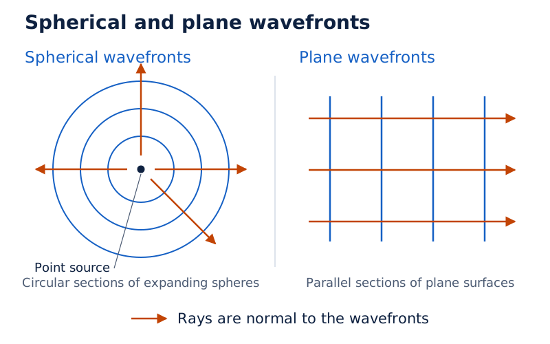
The first drawing shows concentric circular sections of spherical wavefronts with outward arrows. The second shows parallel plane surfaces crossed by arrows indicating propagation.
Drawn by One Young India. See Fig. 10.1 in your NCERT textbook
A wavefront is therefore not a ray. A ray indicates a direction; a wavefront connects points with a common phase. Keeping these two ideas distinct makes the geometrical constructions for reflection and refraction easier to interpret.
How does Huygens’ principle construct a new wavefront?
What are secondary wavelets?
Huygens’ principle treats every point on a wavefront as a source of secondary disturbances. These secondary wavelets spread through the medium at the speed of the wave. Their forward common envelope gives the position of the wavefront at a later instant.
Let denote the wave speed and the elapsed time. Each secondary wavelet has radius . The S.I. unit of wave speed is metre per second, written . The S.I. unit of elapsed time is second, written .
- Start with the known wavefront and choose points distributed along it.
- Draw a secondary wavelet centred at each chosen point, using the radius for the same elapsed time.
- Construct the common tangent surface on the forward side of the wavelets.
- Identify this envelope as the new wavefront, and draw rays normal to it.
For a spherical wavefront in a uniform medium, the construction produces another spherical wavefront with the same centre. For a plane wavefront, all wavelets have equal radii, so their forward envelope is another plane parallel to the original plane.
What the figure shows
Forward envelope of secondary wavelets
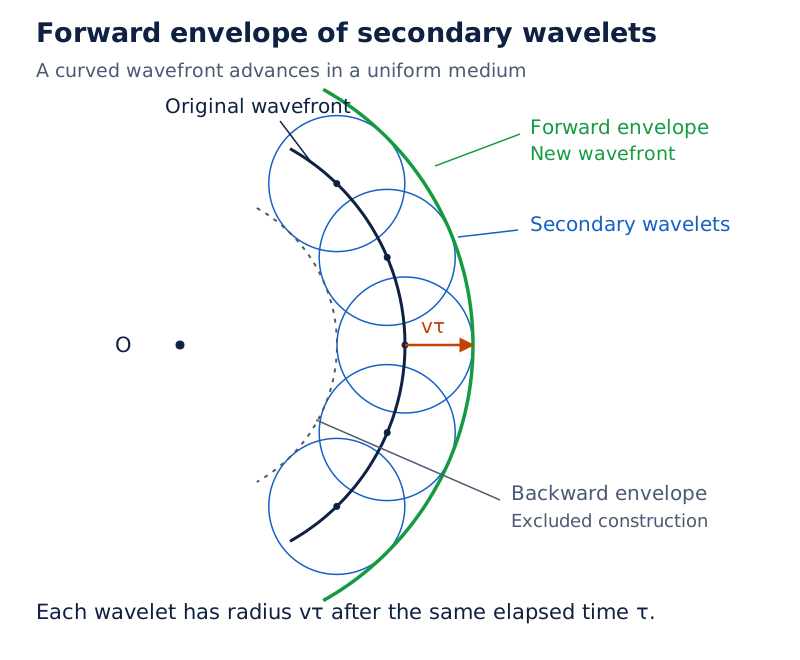
An inner curved wavefront carries several points from which small wavelets are drawn. Their outer envelope forms the new curved wavefront. A dotted inner construction represents the proposed backward envelope.
Drawn by One Young India. See Fig. 10.2 in your NCERT textbook
Why is the forward envelope selected?
The elementary construction also suggests a backward envelope. Huygens assumed maximum wavelet amplitude forwards and zero amplitude backwards to exclude it. This assumption is a limitation of the original construction; a more rigorous wave theory accounts for the absence of that backward wave.
The useful result is the forward envelope rule. When light reaches an interface, different parts of the incoming wavefront arrive at different times. Constructing their secondary wavelets in the appropriate medium explains why the resulting wavefront changes orientation.
How does Huygens’ principle give Snell’s law?
Consider a plane wavefront reaching an interface. Point reaches the interface first, while point travels to point . Let and be the speeds in the incident and transmitted media, respectively.
Let be the angle of incidence and the angle of refraction, both measured between their rays and the normal. Let be the speed of light in vacuum, and and the refractive indices of the two media.
Derivation: Refraction at a plane interface
- During the elapsed time , the incident disturbance travels from to :
- The secondary wavelet from enters the second medium. If is its point of contact with the tangent drawn from , its radius is The tangent is the refracted wavefront.
- The two right triangles share the interface segment . Their geometry gives
- Dividing these expressions removes the common distance and time:
- Use the refractive-index definitions Substitution gives
Result: Snell’s law follows from the different distances travelled by secondary disturbances in the same time. When the transmitted medium has a lower wave speed, the refracted ray bends towards the normal.
What the figure shows
Refraction of a plane wavefront
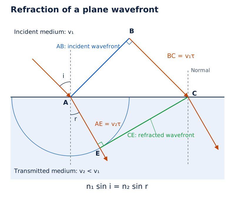
A horizontal interface separates two media. The incident wavefront joins points and , while the refracted tangent joins and . Normals, incident rays and refracted rays show the change in direction.
Drawn by One Young India. See Fig. 10.4 in your NCERT textbook
What changes at a rarer medium?
When light passes into an optically rarer medium, its speed increases and its ray bends away from the normal. For light travelling from higher to lower refractive index, define the critical angle by
At this angle, the angle of refraction is . For an incidence angle greater than the critical angle, there is no propagating refracted ray in this construction and total internal reflection occurs. Both the direction of travel and the angle condition matter.
How are reflection and focusing explained using wavefronts?
Derivation: Reflection at a plane surface
Let be the incident wavefront and the reflecting surface. Point reaches the surface first; point reaches after time . Here denotes the reflection angle, and is the speed in the common incident and reflected medium.
- The incident disturbance travels the distance
- Draw the reflected secondary wavelet from . Its tangent point satisfies
- The triangles and are right triangles with common hypotenuse and equal sides and . They are congruent.
- Corresponding angles therefore give the reflection law The reflected wavefront is the tangent .
Result: The incident and reflected rays make equal angles with the normal. Unlike refraction between different media, the construction uses the same speed for both portions of the journey.
How do optical elements reshape a wavefront?
In a thin prism, light travels through different thicknesses of glass. The part crossing the greater thickness is delayed more because light travels more slowly in glass. This relative delay tilts the emerging plane wavefront and changes the direction of propagation.
In a convex lens, the central portion of an incident plane wave crosses the thickest glass and is delayed most. The emerging wavefront becomes converging and spherical, approaching the focus. A concave mirror also converts a plane wave into a converging spherical wave by reflection.
What the figure shows
Changes in wavefront shape
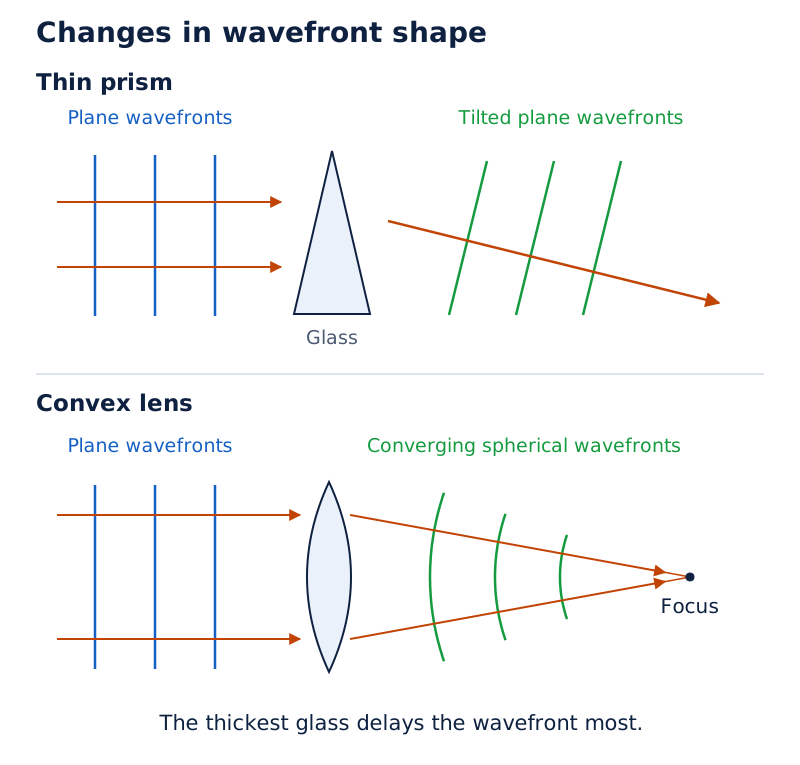
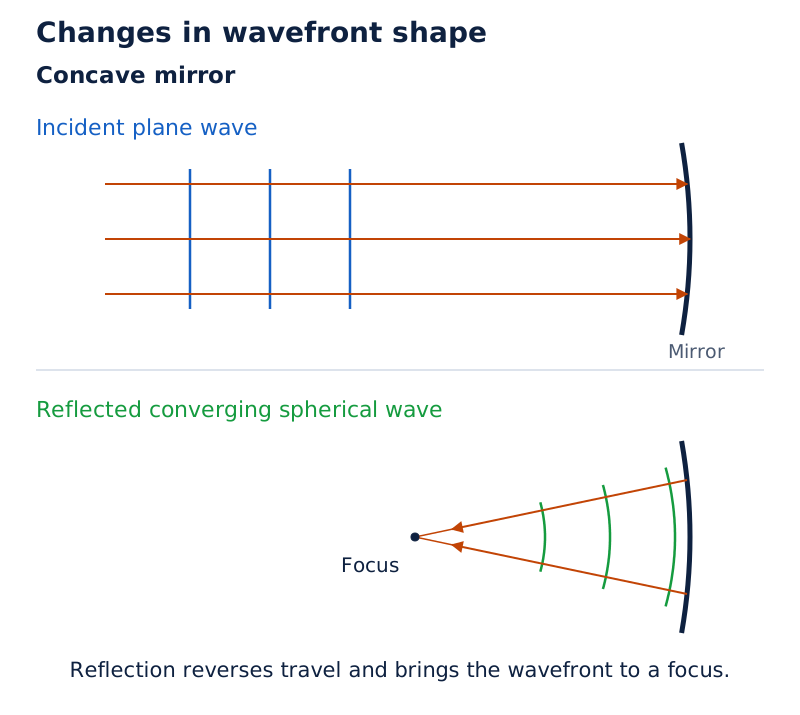
Three drawings show an incident plane wave meeting a prism, a convex lens and a concave mirror. The prism produces tilted wavefronts; the lens and mirror produce curved wavefronts directed towards their focal points.
Drawn by One Young India. See Fig. 10.7 in your NCERT textbook
For rays connecting an object point and its image point, the total travel time is the same. The central ray through a convex lens may follow a shorter geometrical path, but it spends more of its journey in the slower glass. Travel time, rather than geometrical distance alone, explains the common phase at the image.
What happens to wavelength, frequency and speed during refraction?
Which quantity remains unchanged?
Let denote wavelength and frequency. Their relation to wave speed is The S.I. unit of wavelength is metre, written . The S.I. unit of frequency is hertz, written .
At a stationary interface, reflected and refracted light have the incident frequency. The atomic constituents respond to the driving light by forced oscillation at that frequency. A change in propagation speed therefore changes wavelength, rather than frequency.
With and denoting wavelengths in the two media, The refractive index is dimensionless because it is a ratio of speeds.
Worked example 1. Light of wavelength enters water from air. The refractive index of water is . Treat the speed in air as . Find the reflected and refracted frequencies, speeds and wavelengths.
Formula: Let be water’s refractive index. Use and ; the wavelength in water is .
- Substitute: The incident wavelength is Therefore
- The reflected light remains in air:
- The refracted speed is
- The refracted wavelength is
Answer: Both frequencies are . Reflection preserves the wavelength in air; transmission into water reduces it to approximately .
Worked example 2. Glass has refractive index . Find its light speed using .
Formula: With denoting the glass refractive index, .
- Substitute:
- Evaluate the quotient:
Answer: The speed is for the stated refractive index.
A lower speed does not by itself imply that the light wave carries less energy. In the wave description, intensity depends on the square of the amplitude. Speed, wavelength and amplitude describe different properties and should not be treated as interchangeable.
How do coherent waves produce bright and dark regions?
What does superposition add?
The principle of superposition adds the displacements produced by overlapping waves at a point. It does not generally allow their intensities to be added directly. For light, the corresponding electric-field disturbances superpose.
Coherent sources maintain a stable phase difference and have the same frequency. Their interference pattern can remain stationary. Independent ordinary lamps undergo unrelated, rapid phase changes, so they do not normally produce a stable pattern of bright and dark fringes.
Derivation: Intensity for two equal-amplitude coherent waves
Let and denote two displacements, their common amplitude, time, angular frequency and their phase difference. Let be the intensity from either source alone and the resultant intensity.
- Write the two disturbances as
- Add the disturbances: where is the resultant displacement.
- Apply the cosine addition identity:
- Because intensity is proportional to amplitude squared,
Result: The resultant intensity depends on phase difference. The S.I. unit of intensity is watt per square metre, written . Equal source amplitudes are essential for the zero-intensity minimum in this expression.
Let denote the signed path difference and an integer fringe order. For sources initially in phase, Here is the circle constant and phase angles are expressed in radians.
| Condition | Path difference | Result for equal amplitudes |
|---|---|---|
| Constructive interference | , a bright fringe | |
| Destructive interference | , a dark fringe | |
| Rapidly changing relative phase | No fixed phase relationship | Time-averaged intensity |
At a bright fringe, the waves arrive in phase and reinforce each other. At a dark fringe, the equal disturbances arrive in opposite phase and cancel. Between these positions, the intensity takes intermediate values rather than switching abruptly between its extremes.
Energy is redistributed, not destroyed, by interference. Reduced intensity in dark regions accompanies increased intensity in bright regions. For incoherent sources, the rapidly varying interference contribution averages away and the individual intensities add.
How does Young’s double-slit experiment produce equally spaced fringes?
Why illuminate both openings from one source?
Young’s arrangement uses two closely spaced openings illuminated by the same original source. Their outgoing waves inherit the same phase changes, so the openings behave as coherent secondary sources. Simply placing two independent lamps behind two openings does not give this phase relationship.
Let be the slit separation, the distance from the slit plane to the screen, and the transverse distance of an observation point from the central position. The S.I. unit of slit separation is metre, written .
For a distant screen and positions near the centre, the path difference is approximately The approximation applies when the screen distance is much greater than the slit separation and the observation angle is small.
Where do the fringes appear?
Let denote a fringe position of integer order . Bright fringes occur at Dark fringes occur at
The central position has equal paths from the two sources. With the sources in phase, this point is a central bright fringe. Bright fringes occur on either side, with dark fringes between them.
The fringe width means the separation of successive bright fringes or successive dark fringes: The distance from a bright fringe to the adjacent dark fringe is , so it is not the full fringe width.
| Change made alone | Effect on fringe width | Reason |
|---|---|---|
| Increase wavelength | Fringes spread farther apart | Fringe width is proportional to wavelength. |
| Increase screen distance | Fringes spread farther apart | Fringe width is proportional to screen distance. |
| Increase slit separation | Fringes become closer | Fringe width is inversely proportional to slit separation. |
Note: These spacing comparisons keep the other factors constant. They also retain the distant-screen, small-angle approximation used for the fringe-position expressions.
Real openings also diffract light. The full two-slit pattern combines interference between the openings with the diffraction pattern associated with each opening. The equally spaced interference fringes therefore do not imply a uniformly bright pattern over an unlimited screen.
How are interference calculations solved with complete data?
How do measured positions reveal wavelength?
Worked example 3. In Young’s experiment, the slit separation is , the screen distance is , and the fourth bright fringe lies from the central maximum. Find the wavelength and fringe width.
Formula: Use and , with the bright-fringe order .
- Convert the lengths:
- Substitute:
- Express the wavelength conveniently:
- Compute the fringe width:
Answer: The wavelength is , and successive bright fringes are separated by .
The order counts intervals from the central bright fringe. The central fringe has zero order, so the fourth bright fringe is four fringe widths away. Confusing its position with one fringe width changes the inferred wavelength by a factor of four.
How does a path difference determine intensity?
Worked example 4. Two coherent equal-amplitude waves start in phase. Their resultant intensity at path difference is intensity units, where is the stated maximum intensity. Find the intensity at path difference .
Formula: Use and .
- The reference point is a maximum because
- Substitute: At the required point,
- The intensity is
Answer: The intensity is in the original intensity units, or 25% of the maximum. The intensity ratio is dimensionless.
When do fringes from two wavelengths coincide?
Worked example 5. Light contains wavelengths and . For slit separation and screen distance , find the third bright-fringe position for the first wavelength and the least positive coincidence distance. Express both distances in terms of .
Formula: Use . Coincidence requires , where and are positive integer orders, and , are the stated wavelengths.
- Substitute: The third bright fringe for the first wavelength is
- For coincidence, The least positive orders are and .
- The corresponding distance is
Answer: The two distances are and . The geometry ratio is dimensionless when both lengths use the same unit.
A wavelength pair determines the orders that coincide, but it does not independently determine their distance on the screen. The screen geometry must also be specified, either numerically or through the symbolic ratio used here.
Why does a single slit produce a broad central diffraction maximum?
How do different parts of one opening interfere?
Diffraction is the spreading of waves through openings and into regions beyond the geometrical boundary of a shadow. It occurs for light, sound and other waves. For light, its small wavelength makes many everyday diffraction effects difficult to notice.
Consider a parallel monochromatic beam incident normally on a narrow slit. Let now denote the slit width, and let be the angle between the observation direction and the central normal. Different parts of the illuminated slit act as secondary sources initially in phase.
At the centre, their contributions reinforce one another. Away from the centre, the contributions travel different distances and acquire different phases. Their superposition produces alternate dark and bright regions, with a broad central maximum and progressively weaker secondary maxima.
What the figure shows
Single-slit geometry and intensity pattern
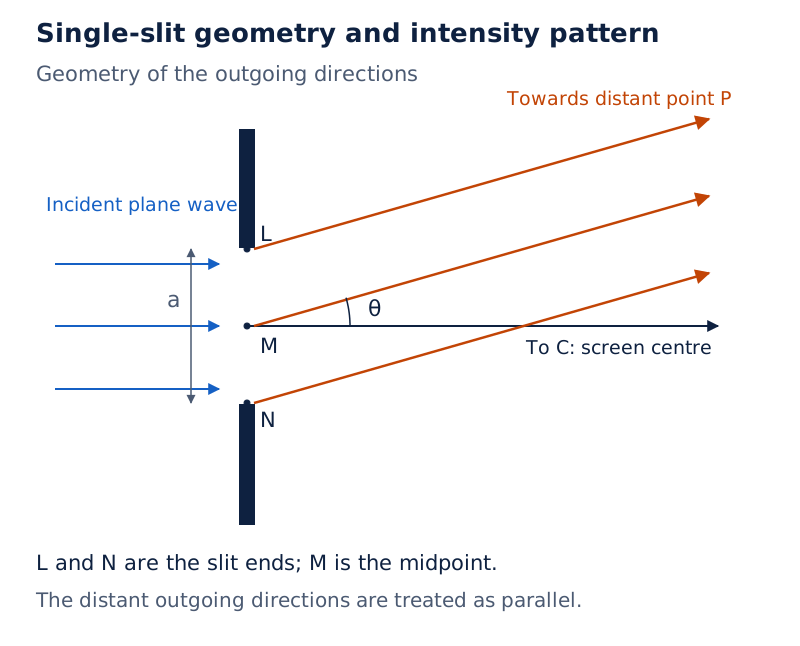
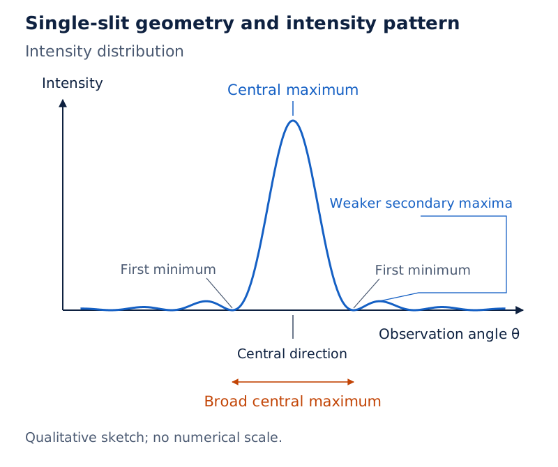
The geometry labels the slit ends and midpoint, with oblique outgoing directions towards an observation point and a central direction towards the screen centre. Photograph: Fringes due to diffraction at a single slit (Figure 10.15). The photograph shows a wide bright central band with narrower, weaker bands beside it. The accompanying diagram shows the intensity distribution.
Drawn by One Young India. See Figs. 10.14 and 10.15 in your NCERT textbook
What controls the spread?
For small angles, the dark directions are approximately Here is the angular position of the minimum of non-zero integer order . The central maximum is bounded by the first minima on opposite sides.
These positions show that a narrower slit gives a wider central region when wavelength remains constant. A longer wavelength also produces greater spreading for the same slit. Thus red-light fringes are wider than blue-light fringes in the same single-slit arrangement.
| Feature | Two-slit interference | Single-slit diffraction |
|---|---|---|
| Contributions compared | Waves from two coherent openings | Waves from different parts of one opening |
| Characteristic pattern | Equally spaced interference fringes near the centre | Broad central maximum with weaker side maxima |
| Underlying principle | Superposition of wave disturbances | Superposition of wave disturbances |
There is no fundamental separation between the physics of interference and diffraction. Both involve adding wave contributions with their phases. The terms usually distinguish the arrangements and patterns being discussed.
Resolution is also limited by diffraction: optical instruments cannot distinguish arbitrarily close objects simply by using ray diagrams. Wavelength therefore sets a physical limit on the geometrical-optics approximation.
How does polarisation demonstrate the transverse nature of light?
What is restricted in plane-polarised light?
In a transverse wave, the disturbance is perpendicular to propagation. For light, the electric vector can oscillate in different directions within this transverse plane. Plane-polarised light has its electric vector restricted to a fixed direction in that plane.
In unpolarised light, the electric-field direction changes rapidly and randomly within the transverse plane. This does not mean that the electric field points along the direction of travel. The field remains transverse even though its direction is not fixed.
A stretched string provides a useful analogy. Moving its end vertically produces transverse motion in one plane; moving the end horizontally produces transverse motion in another. Randomly changing the vibration plane illustrates the distinction between a fixed polarisation and an unpolarised disturbance.
What does a polaroid transmit?
A polaroid contains long-chain molecules aligned in a particular direction. It absorbs the electric-field component parallel to those molecules. The perpendicular direction that is transmitted is its pass-axis.
Unpolarised light passing through an ideal polaroid becomes linearly polarised and has half its original intensity. Rotating that single polaroid does not change the transmitted intensity of the unpolarised incident beam.
A second polaroid behaves differently because the light reaching it is already polarised. With parallel pass-axes it transmits the polarised beam most strongly. With perpendicular, or crossed, axes, the ideal transmitted intensity is zero; experimentally the observed minimum is nearly zero.
What the figure shows
Light through two polaroids
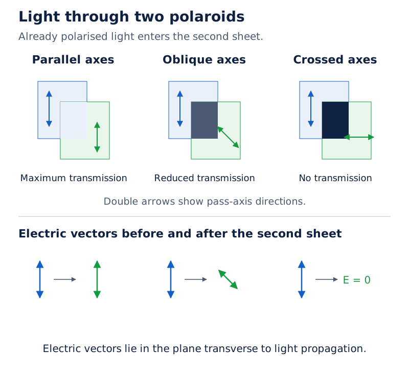
The upper drawings show overlapping sheets at different relative angles, with the overlap becoming dark for crossed orientations. The lower drawings use double arrows to show electric-vector directions before and after transmission through the sheets.
Drawn by One Young India. See Fig. 10.18 in your NCERT textbook
Interference and diffraction also occur for longitudinal waves such as sound in air. Polarisation provides the distinguishing evidence here because it selects among transverse directions of oscillation. It cannot be explained by a disturbance restricted to the propagation direction.
How does Malus’ law determine transmission through polaroids?
Which intensity belongs in the law?
Let be the intensity of linearly polarised light reaching an ideal analysing polaroid, and the transmitted intensity. Let be the angle between the incident polarisation direction and the analyser’s pass-axis.
Malus’ law is It applies to the already polarised beam entering the analyser. If the original beam is unpolarised, first account for the halving of intensity at the first ideal polaroid.
Derivation: The intensity projection rule
Let denote the incident electric-field amplitude and its transmitted component.
- Resolve the incident electric vector along the pass-axis:
- Relate the intensity ratio to the squared amplitude ratio:
- Substitute the projected amplitude to obtain
Result: Transmission varies between the full incident polarised intensity and zero as the relative angle changes from parallel to crossed axes. Rotating an analyser through a full turn gives two maxima and two minima.
Worked example 6. Insert a third ideal polaroid between two crossed polaroids. Let be the intensity after the first sheet, and let the middle sheet make an angle with the first. Find the transmitted intensity and its maximum fraction of .
Formula: If and are the intensities after the middle and final sheets, use and .
- The last two pass-axes make angle , so
- Use the double-angle identity:
- Substitute: At ,
Answer: Maximum transmission is 25% of the intensity after the first polaroid. This is a dimensionless ratio; all three intensities use the same intensity unit.
The middle sheet changes the polarisation direction of the transmitted component. The final sheet can therefore receive a non-zero component along its own axis, although the original first and final sheets remain crossed. Polaroids use this control of intensity in sunglasses, windowpanes and cameras.
Glossary
- Wavefront — A surface joining points of a wave that oscillate in the same phase.
- Ray — A line indicating energy propagation, normal to the wavefront in an isotropic medium.
- Secondary wavelet — A disturbance emitted from a point on an existing wavefront in Huygens’ construction.
- Refractive index — The ratio of light speed in vacuum to its speed in the specified medium.
- Coherent sources — Sources with the same frequency and a stable phase difference during observation.
- Superposition — The addition of individual wave disturbances to obtain the resultant disturbance at a point.
- Constructive interference — Reinforcement of overlapping waves that arrive in phase, producing an intensity maximum.
- Destructive interference — Cancellation of overlapping out-of-phase disturbances, complete when their amplitudes are equal and opposite.
- Fringe width — The distance between successive bright fringes or successive dark fringes in an interference pattern.
- Diffraction — Wave spreading through apertures and beyond the boundary predicted by a geometrical shadow.
- Plane polarisation — Restriction of a light wave’s electric-vector oscillations to a fixed direction perpendicular to propagation.
- Pass-axis — The direction along which a polaroid transmits the electric-field component of incident light.
Common errors and misconceptions
- Misconception: A wavefront is the path followed by a ray. Correct: It is a constant-phase surface; rays are normal to it in the isotropic medium considered.
- Misconception: Light’s frequency falls when it slows in glass. Correct: Frequency remains unchanged at the stationary interface, while wavelength decreases with speed.
- Misconception: Two lamps of the same colour automatically give stable fringes. Correct: A stable phase difference is also necessary; independent ordinary lamps do not maintain it.
- Misconception: Intensities can always be added for overlapping light waves. Correct: Add disturbances first for coherent waves; an interference contribution changes the resultant intensity.
- Misconception: Fringe width is the distance between an adjacent bright and dark fringe. Correct: It is the distance between successive fringes of the same kind.
- Misconception: A narrower slit gives a narrower diffraction pattern. Correct: With wavelength unchanged, reducing slit width increases the angular spread.
- Misconception: Malus’ law directly uses the original unpolarised intensity. Correct: It uses the polarised intensity incident on the analyser, after the first ideal sheet has halved unpolarised intensity.
- Misconception: Dark fringes show destruction of light energy. Correct: Energy is redistributed between bright and dark regions without a net gain or loss.
Exam-style questions with model answers
Q1. Define a wavefront and state its relationship to a ray in an isotropic medium. [2 marks]
- A wavefront is a surface connecting points that oscillate in the same phase.
- A ray indicates energy propagation and is perpendicular to the wavefront in an isotropic medium.
Q2. Why do two independent ordinary lamps fail to produce sustained interference fringes, whereas two openings illuminated by one source can do so? [3 marks]
- Sustained interference requires waves of the same frequency with a stable phase difference. Otherwise the positions of maxima and minima change during observation.
- Independent ordinary lamps undergo unrelated rapid phase changes. Their interference contribution averages away, leaving the sum of their separate intensities.
- Two openings illuminated from one original source inherit its phase changes together. They can therefore act as coherent secondary sources and produce a stationary fringe pattern.
Q3. Use Huygens’ construction to derive Snell’s law for a plane wavefront crossing a plane interface. Define the speeds, indices and angles used. [5 marks]
- Let and be the wave speeds, and and the refractive indices, in the incident and transmitted media. Let and be the angles their rays make with the normal.
- Let on incident wavefront reach the interface first. During elapsed time , point reaches point , giving
- The secondary wavelet from has radius . The tangent is the refracted wavefront. Geometry gives
- Dividing yields
- With vacuum speed , substitute and . Hence A lower transmitted speed therefore corresponds to bending towards the normal.
Q4. Light of wavelength enters water of refractive index from air. Take the speed in air as . Calculate its frequency, speed and wavelength in water. [3 marks]
- Let be frequency, the speed in water and its wavelength. Frequency remains unchanged at the interface:
- Divide the vacuum-approximated air speed by the given refractive index:
- The wavelength decreases in the same ratio as speed: Thus frequency is preserved while both speed and wavelength decrease.
Q5. In Young’s double-slit experiment, slit separation is , screen distance is , and the fourth bright fringe is from the central maximum. Find the wavelength and fringe width. [3 marks]
- Let be slit separation, screen distance, the fourth-fringe position, wavelength and fringe width. Convert the measured lengths:
- The fourth bright fringe is four fringe widths from the central maximum:
- Its position therefore gives This is the separation of consecutive bright fringes, not adjacent bright and dark fringes.
Q6. Describe the single-slit diffraction pattern and explain how decreasing slit width or increasing wavelength affects its central region. Keep the screen arrangement unchanged. [3 marks]
- A normally illuminated narrow slit produces a broad central bright maximum, with alternating dark regions and weaker secondary maxima on both sides.
- Different parts of the slit act as secondary sources. Their waves reinforce at the centre but arrive with different phases in other directions.
- Decreasing slit width increases the spread when wavelength is fixed. Increasing wavelength also increases the spread for a fixed slit width. The changes follow from the dependence of the dark directions on the wavelength-to-width ratio.
Q7. Starting with superposition, derive the resultant intensity for two coherent waves of equal amplitude and identify their maximum and minimum intensities. Define all symbols. [5 marks]
- Let be each wave’s amplitude, its angular frequency, time and the stable phase difference. Let , and be the individual and resultant displacements:
- Superposition adds the displacements, so
- The trigonometric addition identity gives Thus the squared resultant amplitude depends on the relative phase.
- Let be the intensity of either wave alone and the total intensity. Since intensity is proportional to amplitude squared,
- For integer , maxima occur at , giving . Minima occur at , giving . Equal amplitudes make this complete cancellation possible.
Key takeaways
- A wavefront connects equal-phase points, while rays indicate energy propagation normal to the wavefront in an isotropic medium.
- Huygens’ principle constructs a later wavefront as the forward envelope of secondary wavelets emitted from the earlier wavefront.
- Refraction changes speed and wavelength together, while frequency remains unchanged across a stationary interface.
- Coherent sources maintain a stable phase difference, allowing interference maxima and minima to remain stationary during observation.
- Young’s fringe width increases with wavelength and screen distance, but decreases with increasing slit separation.
- Single-slit diffraction produces a broad central maximum with weaker side maxima; a narrower opening increases the spread.
- Interference and diffraction redistribute energy, so dark regions are accompanied by enhanced intensity elsewhere.
- Polarisation reveals transverse oscillations, and Malus’ law uses the polarised intensity reaching the analysing polaroid.
Test yourself
What wavefront is produced by a uniformly radiating point source?
A diverging spherical wavefront, with successive surfaces centred on the point source.
Why can a distant spherical wavefront be treated as plane over a small region?
Its curvature is negligible over that small region compared with the sphere’s large radius.
Which two quantities decrease when light enters a medium of greater refractive index?
The wave speed and wavelength decrease, while the frequency remains unchanged.
Why can two openings illuminated by one source act coherently?
Both inherit the same source phase changes and can maintain a stable relative phase.
What happens to Young’s fringe width if slit separation increases while the other quantities remain fixed?
It decreases because fringe width is inversely proportional to the slit separation.
Why does a dark interference fringe not violate energy conservation?
Wave superposition redistributes energy, reducing intensity in dark regions and increasing it in bright regions.
What happens to single-slit diffraction when the slit becomes narrower at fixed wavelength?
The diffraction pattern spreads more widely and its central bright region becomes broader.
Why does rotating a single ideal polaroid not change transmission of unpolarised light?
The incident electric-vector directions vary randomly in the transverse plane, so each orientation transmits the same average intensity.